I have an old Raspberry Pi running Volumio to stream my music library to my living room home theatre. This morning, I needed to perform an update from Volumio 3 to Volumio 4. After I did the upgrade, the Raspberry Pi acquired a new IP address, which I need to discover through my Unifi Dream Machine Pro (UDMPro) Max web based user interface. It is then that I noticed that all the virtual machines hosted using Proxmox running on our AI Server have dropped off from my network. This is the AI Server that I built back in August of 2023, and discussed in this post.
I thought all I needed to do was a reboot, still no network connection. The networking interface seems to be off. I plug in a keyboard into the server, and added a monitor. No video signal, and the keyboard did not respond, not even the NUMLOCK LED worked. This is not good. All signs point to a hardware failure.
I pulled out PCIe cards one by one and try to resuscitate the server. No good. With a bare-bones motherboard, memory, and CPU, it still did not respond. I couldn’t even get into the BIOS. The fans were spinning, and the motherboard diagnostic LED’s point to some error when it is trying to initiate video / VGA.
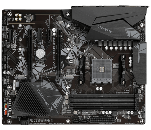
I ended up finding a possible replacement motherboard, Gigabyte B550 Gaming X V2, at a local Canada Computers for $129 (before tax), and some thermal paste for $9.99 (before tax) to reseat the CPU and the cooler.
Replacement Board
The good news is that after replacing the motherboard, I was able to get into the BIOS. However when I try to boot the machine with the used Nvidia P40 card, it failed to boot again. I had to forego this card. The GPU could have been damaged by the old mainboard, or the GPU could have been damaged first and caused the mainboard to fail. At this point I am too tired to play the chicken or the egg game. I simply left the card out, and restore Proxmox on the server. It will no longer be an AI server, but at least the virtual machines on the server can be recovered.
Proxmox boots but will not shutdown. I had to undo the PCIe passthrough configurations that I did when I build the AI Server. This involved editing the GRUB configuration so that all the special options are removed in /etc/default/grub:
GRUB_CMDLINE_LINUX_DEFAULT=""
Before it had configurations containing options to make use of IOMMU and the vfio modules. After this update, I had to perform the following commands:
update-grub
update-initramfs -u -k all
I then proceed to reboot the system, and the system behaved normally. During this process I also found out that Proxmox will not start normally if any of the mounts configured in /etc/fstab are not available. This threw me for a loop because the regular USB backup drive was disconnected when I was trying to resolve this issue.
Since the PCIe bus has different peripherals, I knew from my past experience which I detailed here, I have to edit the /etc/network/interfaces file with the new interface name. The following command really helped me identify the new name and which NIC I should pick, because there were multiple interfaces, and I wanted to pick the 2.Gbps one.
lshw -class network
In the end, all of the virtual hosts are now up and running. I hope this new motherboard proves to be more stable without the used P40 GPU. Fingers crossed!
I purchased the patch panel from Amazon back in June of this year. Today I finally got around to installing it. One of the main reasons for the delay was that I had to properly ground the patch panel to an electrical outlet. I did this with an old PC power cable and solder the ground wire only to the metal frame of the patch panel.
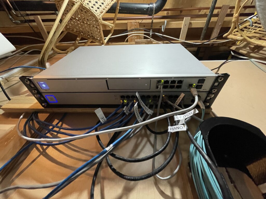
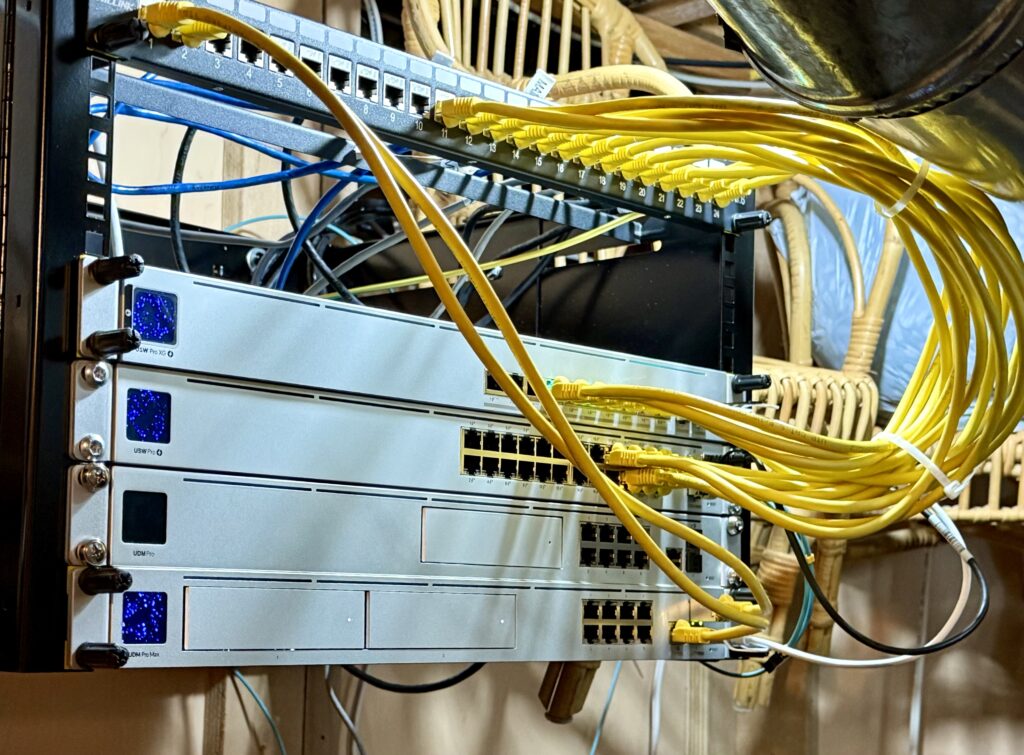
In addition to the patch panel, I also purchased this wall mountable network rack. This 7U rack has enough room for our new 10Gbps networking equipment that I talked about in this post. These included the UDM Pro Max router / firewall, and our 10Gbps networking upgrade with our new USW Pro XG 10 PoE switch.
We also upgrade some of the satellite switches in the house with:
Using the UDM Pro Max, we can have dual Internet Service Providers (ISP). We are currently using TelMax and Rogers with a 75% and 25% traffic split, respectively. If one goes down, the other automatically pickup all the traffic, so we have Internet redundancy.
The UDM Pro Max allows us to have our old UDM Pro to be a cold stand-by in case the unit fails.
I think we can all agree that the latter 10Gbps system is much neater. I’m quite happy with the reorganization and the upgrade.
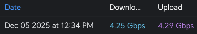
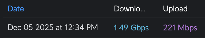
After all of this, we now have the most current speed tests:
The above shows the TelMax speed test.The above shows the Rogers speed test.
Today is the first time that I register advertised speed with my TelMax subscription.
Now our household wired networking infrastructure is ready for WiFi 7 upgrade. That is a project for next year.
Recently, I added TelMax as our Internet Service Provider. One of the requirements for their service is an externally accessible IP address. When the service was provisioned this past September, this requirement was satisfied. However, in the middle of this month (November), the service was switched to CGNAT. You can click on the link to learn more about CGNAT, but effectively, after their CGNAT rollout, I no longer have an externally accessible IP. This was frustrating, especially when I was in China working remotely and depended on this external IP. I understand that TelMax wants to tier their services so that a dedicated IP address is in a higher tier service. However, to make this change unannounced and unscheduled is really not professional. Their sales staff at the time also promised that an external IP will be available as part of the residential offering; clearly, it was not, so buyers beware.
Long story short, this past Friday, I called into their customer service and had my service upgraded to a business service where a dedicated IP is part of the offering. Kudos to the customer service rep who handled the migration and provisioning. This new service also gave me 4Gbps symmetrical throughput, so that is a nice to have.
Unfortunately, the service did not last, and in about four hours, the service went down. Since this happened off business hours, I called back on Saturday morning. TelMax first line support during non-business hours is effectively useless. The result of the Saturday call was, “Thank you for the information; sorry about your situation; and someone will get back to you.” Very open-ended without a commitment for a time range of resolution. You are effectively left hanging. Apparently, today I learned that it can be up to 72 hours for someone to get back to you. This is clearly not acceptable for a business account, in my opinion.
On Sunday, feeling frustrated and unloved by TelMax, I went to their online portal and wrote a lengthy support email describing my situation. Crickets, not even an auto reply email. I called them on Monday and got hold of their tier 2 support and tried to get the service back up and running. Full disclosure here. At this point, we all thought the issue was at TelMax and not with me. My firewall was working fine because the rest of my network is humming along. We even switched out the cable thinking the cable may be defective. I asked whether there is any way to verify that ethernet port labeled 10GE on the fibre modem is working or not. He told me it is working. I found it strange why there is no physical link indicator then? He decided to escalate the issue, and the call ended.
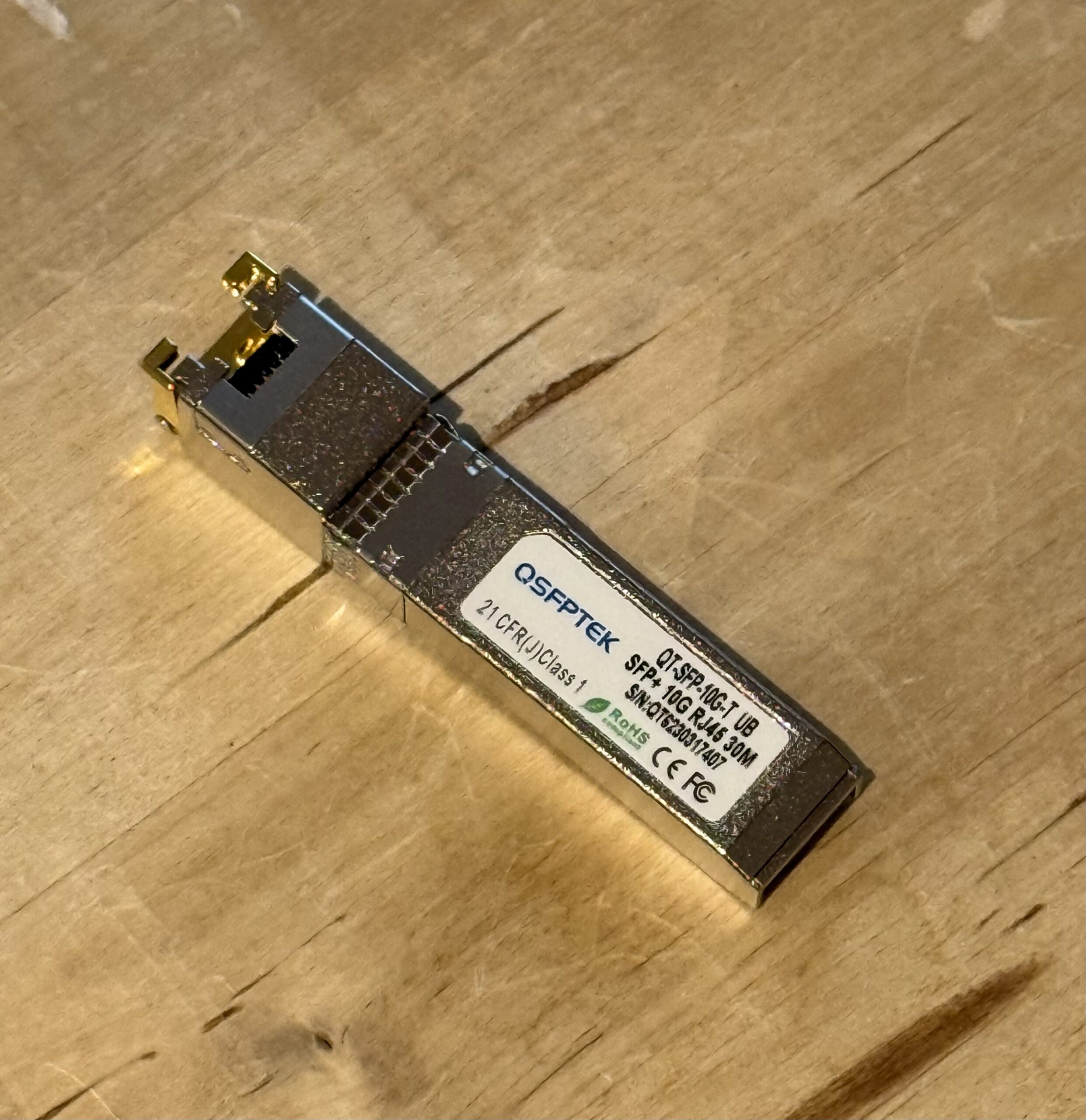
2+ years old SFP+ module failed
No one got back to me for the entire Monday. Today I woke up and decided to use my spare laptop to directly test the 10GE port on the fibre modem, and behold there was activity! This confirmed that TelMax equipment was fine at least electrically. The problem must reside with my equipment. I swapped out the SFP+ module with a new one and the physical connection was resolved. Whew!
Since TelMax connections are bound to the physical network interface ID (MAC address), I still had to call into customer support this morning and talked to another tier 2 support rep named Sue. She was wonderful and much more knowledgeable. A few minutes later she had it resolved by rebinding the service to the new SFP+ module’s MAC.
Take aways from these collective events:
TelMax should not switch their networking architecture unannounced and unscheduled when it impacts existing customer experiences. I spent literally hours in China trying to resurrect services with CGNAT. Ultimately, I had to switch back to a backup Rogers connection.
When your ISP is down, don’t assume it is just their fault even though 99% it is. 😁
TelMax support staff’s technical knowledge can range from nothing to super helpful. On the Monday call, the staff should have advised me to use a spare laptop so that we can eliminate my networking equipment as the issue. In fairness, I should have caught this as well, but I’m a bit rusty and I am the stupid customer here.
The TelMax support experience is too open-ended. There is no ticket, no status check, nothing.
In the end, I was in the driving seat to resolve this issue, and it was not TelMax. This is not a good customer experience. I wish TelMax would improve their support capabilities and perceptions as fast as possible. I wish them luck.
I recently was in a situation where I am remote and all of my standard VPN clients stopped working. All I had was a private opened ssh port to my remote server. Luckily I had the foresight to setup this private port before I left home!
I was able to get certain SOCKS to work using the ssh -D option, like:
With this I was able to browse the basics after making the required SOCKS configuration with my WiFi network settings. However, accessing hosts on my private network is still an issue. I can also get macOS Screen Sharing to a specific remote host (e.g. HOST2) to work by establishing a port tunnel using:
I then proceeded to create a Screen Sharing session using port 5901 instead of the default 5900 on my localhost.
With the help of chat.deepseek.com, I was able to discover a nice tool called sshuttle. This seems like the perfect solution for me. Unfortunately I was not able to install sshuttle because GitHub was blocked where I am. I had to install the utility manually. First, I had to configure my local git environment to use the SOCKS server that I created earlier.
Now that everything is working. I then install sshuttle properly with brew.
HOMEBREW_NO_AUTO_UPDATE=1 brew install sshuttle
Once this is done, I removed the temporary install at ~/Applications/sshuttle and rerun the sshuttle using the brew version.
Everything is now working the way that I want. Effectively, it is as good as a VPN with all traffic being routed through my private ssh connection. Thanks to modern AI tools like DeepSeek I was able to figure this out.
Last month one of my SolarEdge inverters stopped generating power. I called New Dawn Energy and they had SolarEdge to remotely diagnosed the system. It turned out this time, it will take more than a simple firmware update. A replacement is approved through their RMA process. This all happened on August the 22nd.
This is the second replacement in three years of operations. SolarEdge really needs to improve their quality process.
Today, the unit finally got replaced after 25 days. During this time 50% of my total solar power was dormant. For something that you think should be part of utility, this is certainly a very long lead time for replacing something that I think would be pretty critical if I was off-grid. Glad I was not!
TelMax started to roll out their fiber infrastructure in my neighborhood during the summer. Last month, a sales team knocked on my door and asked whether I was interested in switching. I told them I was, and it was the symmetrical 2Gbps speed that caught my attention. I also shared my concerns:
The ability to establish bridge mode with an external IP address;
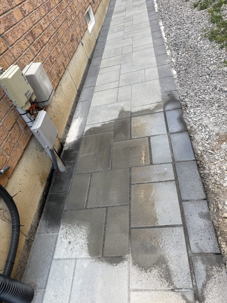
I have interlock bricks on the side of the house, so I wanted to ensure the installation was clean and neat with the interlocks;
I have the flexibility to where I terminate the fibre cable in my basement;
The sales person told me all of my issues will be addressed to my full satisfaction. I inquire how long will it take for the installation process? They told me it should be up and running within 30 minutes.
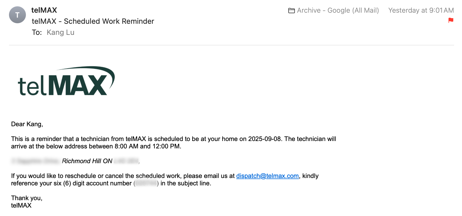
I took the plunge decided to sign up on the last week of August, and got an appointment for September 8th (today) for installation. The appointment is suppose to be today from 8am to 12pm, see the email below:
Email from TelMax from the day before.
The installer came at 11:49am and told me that the installation is broken into two parts. He is just the first part, which is to install a fibre cable from the side of the house and into the house where I would like the modem and WiFi units to be. Since I didn’t care for the Eero units, I left them in the box and instructed the installer where he can place the Adtran modem. This part of the installation was fairly painless. Overall I think the installer was courteous and did a pretty good job running the wire in my basement.
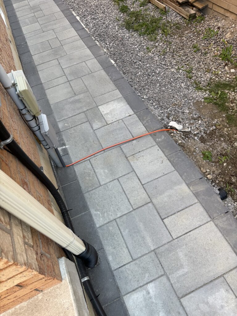
After the second party connected the fibre cable to the curb.
The second part of the installation came around 2 hours later. They installed a flexible, orange conduit that contains a fibre cable from the curb to the side of the house. I told him that I have interlock bricks by the side of the house, and then to my surprise he said that they don’t handle the interlocks. Another party will come later to fix the interlock.
Once again we are in a waiting mode with a safety hazard on my interlock. There is again no expectations set, no scheduling, no appointments. We are now with more anxious waiting. I guess that is how it goes.
Where we are now as of 5:26pm:
Wait for the interlock guys to come;
The modem still shows a red LED so not yet connected;
Feeling a little anxious because the promised of 30 minutes has turned into a drip by drip installation experience by different parties providing services for TelMax but not really from TelMax;
TelMax is a typical case of over promise and under deliver. For a new service being introduced to a new neighbourhood, its opportunity to shine has been turned into mixed feelings of anxiety and customer service uncertainties. This is NOT how you should roll out a brand new service in my opinion.
Update September 8, 5:30-6:00pm:
I logged into the TelMax site and logged in. I contacted their customer support via email and indicated my current status. There was no ticket generated, so we will see what happened.
The process is still fluid, and I will update this as the installation process continues.
Update September 8, 6:11pm:
Someone called me from TelMax provisioning team (not their customer support team) and wanted to know the status of the modem. I told him the optical LED on the modem is still red and he confirmed that there is still a line integrity issue.
This call was not the result of my previous support email that I sent. I also took the opportunity to let him know about the outstanding interlock brick issue, and he told me that is a separate team.
Net-net, they will have to send someone out tomorrow to check the line. I am lucky to be working from home otherwise not sure how other customers can deal with this fluid situation.
Update September 9, 11:49am:
Called TelMax customer support at 1-844-483-5629 spoke to a wonderful lady and told her of my situation and inquired about what is the next step, since I have no visibility on when this will be resolved. She told me that she coordinated with dispatch and that someone, named Bill, will be coming between 4pm to 8pm this evening.
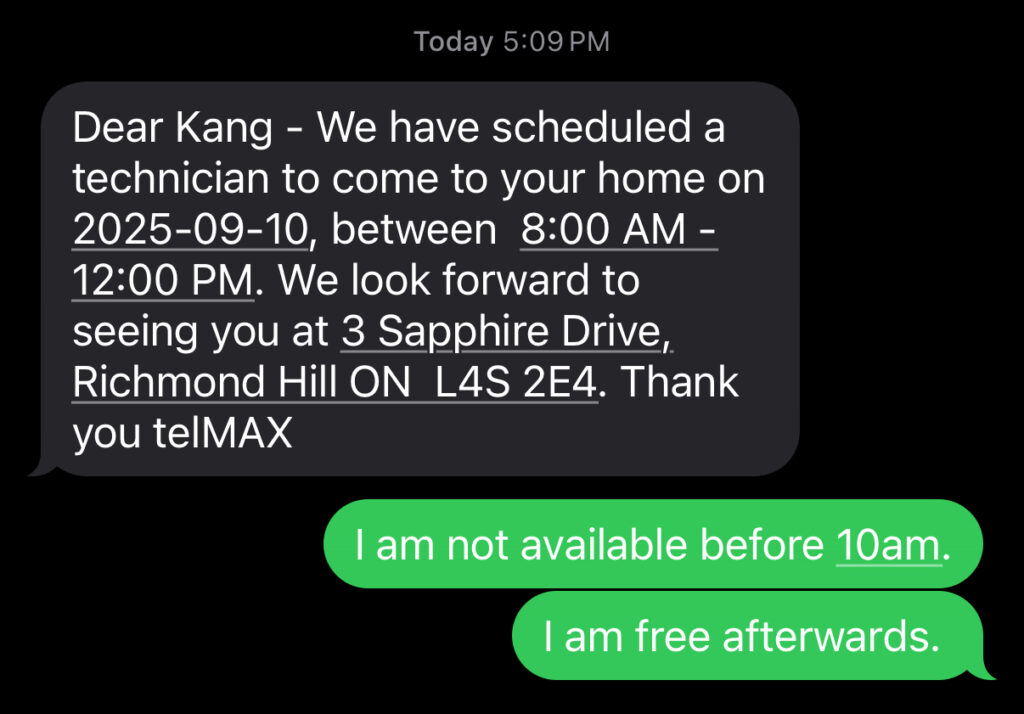
Update September 9, 5:09pm:
I received a text message from 1-289-212-4413 at 5:09pm.
Once again another let down. I freed my evening in preparation for the visit, to learn from the above text message that it is now moved to tomorrow morning, which I am only partially available. Perhaps I am not being patient enough, but I am beginning to feel from frustrated to annoyance.
Update September 10, 1:16pm:
A technical service guy came near noon. His name is Carlo, and he was the first person who I felt really know what he’s doing. Kudos to both Carlo and Peter in identifying the cabling issue and completed the provisioning. Now we are up and running. Problem solved!
Update September 12, 11:56am:
TelMax sent an email to me indicating that the installation process is completed, which is largely true since I am now using their Internet service. However the interlock bricks and the exposed fibre cable is still an outstanding issue. I just sent an email to their support for follow up. So far, no responses.
Update September 16, 6:33pm
This morning at around 8am I called customer support to enquire about the interlock bricks, because the wire is still exposed and it has been more than a week since initial engagement for the deployment. The customer service rep was trying to be helpful but the net-net result is that he listened and took notes. We ended the call with him promising me that someone will call me today to follow up.
We are now in the evening, and no one has called. I also took the opportunity to reach out to the original sales staff, who to their credit is trying to help me out. So with another day gone, the orange wire is still a safety hazard on my pathway. I still do not have an idea of when this will be resolved.
Update September 16, 6:47pm
After venting out my frustration by writing the previous update, I finally decided to just contact my landscaping contractor who originally did my interlock and get it fixed. They got back to me immediately with a timeframe of either Friday or Monday. It is wonderful to deal with professionals. No fuss no muss. No customer support that never gets back to you. I felt like a load off my shoulders.
Yes this is additional cost but I rather pay to get a good night sleep and lower blood pressure.
Update September 17, 5:06pm
About an hour ago DHM, a wonderful interlock contractor showed up and told me that TelMax asked them to come and fix up my interlock. They did excellent work, and the line is finally suppose to be where it is, below the ground and underneath the bricks.
The person from DHM were great guys, and I thanked them profusely. Their workmanship was topped notch!
So all in all it took 9 days from September 8th until now. We can finally claim that the deployment is completed and the service is working normally. Given the multi-party or contractors involved for the deployment, I personally think TelMax could have made things easier and put my mind at ease by keeping me the customer fully informed of the status. They failed in the coordination, and turned what could have been a wonderful experience into one filled with anxiety and frustration. I hope they learn from this will treat future deployment with proper communication.
I want to put in a special thanks to Khushboo Mistry, who really helped me in coordinating and navigating within the TelMax team to finally get this done. As a person on the Sales team, this was not part of her job. She really did above and beyond for me. For this, I really thank her for it.
So in conclusion, here is my assessment:
A – for Internet service;
A – for professionalism of all staff involved; from sales, technicians, and to the DHM the contractor who fixed my interlocks;
F – for communication and customer support department; mainly for unpredictable planning and scheduling; non-existent feedback loop; and no commitment and expectation setting;
It is unfortunate to have one part of the organization to spoil the experience. I wish they will fix their customer support and scheduling process. It is people like Khushboo who will make TelMax a great company, and not the poor organized deployment and installation process that someone else in the company came up with.
In a previous post, I talked about upgrading to the UDMPro Max. This was in preparation for upgrading a series of new switches in the house. Effectively bringing our networking speed from 1Gbps to 10Gbps or 2.5Gbps for most of the house devices. Some home automation devices, TV’s, and other media devices will remain at 1Gbps, since this is plenty for what they need.
Another major reason for upgrading the switching speeds is to prepare for WiFi 7 upgrade. Most of the access points supporting WiFi 7 now require at least a 2.5Gbps wired connection in order to take advantage of the full WiFi speed improvements.
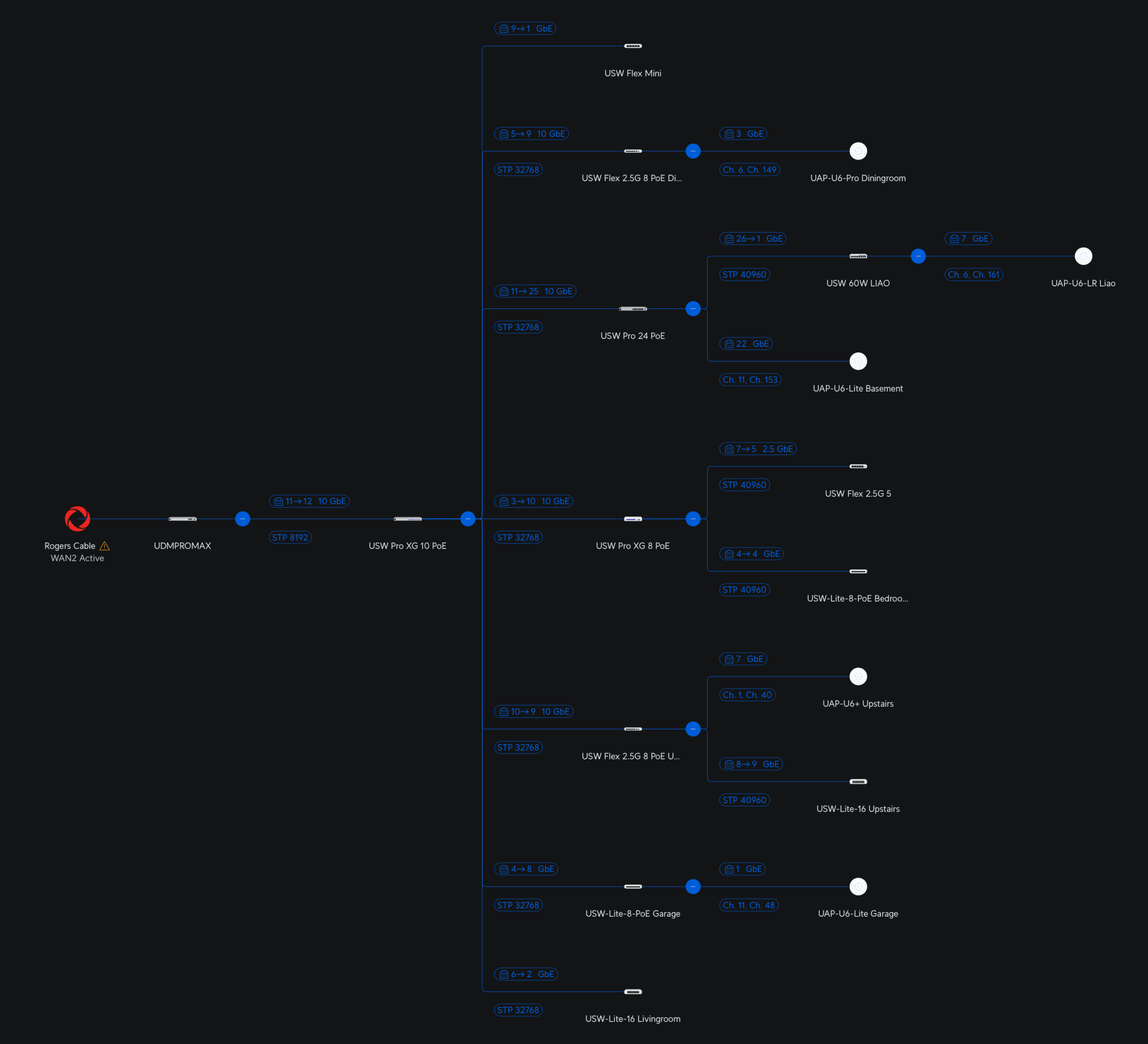
Below is my updated networking landscape for now.
Current networking landscape after several switch upgrades.
New hardware:
1 x UDMPro Max
1 x USW Pro XG 10 PoE
1 x USW Pro XG 8 PoE
2 x USW Flex 2.5G 8 PoE
Old hardware (kept as cold standby):
1 x UDMPro
1 x US 24 250W
1 x USW 60W
The last major upgrade was performed about 4 years ago, as outlined by this post. We also installed fibre about 5 years ago and we talked about it on this post, when we added the USW Pro 24 PoE switch with SFP slots.
I won’t get into the specifications, other than to say the Max offers more speeds and feeds.
I wanted to document the migration process, because for me it was not trivial. The Max came with outdated firmware. The backup and restore options were not visible with a user that had “Super Admin” role. They are only available with the “Owner” role. This took me sometime to figure out.
Step 1: Login into the old UDM Pro with the Unifi owner account. This is usually the account that contains the Two Factor Authentication;
Step 2: Perform a download of all the applications and their respective settings. This should result in unified_os_backup_*.unifi file;
Perform a backup on the old UDM PRO
Step 3: If you are using Protect (Unifi Security Application), and want to reuse the old hard drive, the migration process will not migrate the videos, so be prepare to backup the contents on a separate machine and reformat the hard drive, or just buy new hard drives;
Step 4: I powered down the old UDM Pro, because I need the WAN connection to be connected to the new UDM Pro Max. At this point, you will lose Internet connectivity for most of your household devices;
Step 5: I physically installed the UDM Pro Max, and connected the WAN, and connected my laptop with the unifi backup file that we got in Step 2. Note that I did not connect the rest of my network at this point. Also the entire restoration process requires Internet connectivity so don’t try to restore it without Internet. I learned this the hard way, resulting in several resets;
Step 6: I had to upgrade the UDM Pro Max because it came with old firmware and it will not restore with the old firmware. This was super frustrating because it elongated the down time for your household;
Step 7: Before I perform the restore, I powered down the Max and installed my old hard drive from the old Pro. After restarting the Max, I then reformat the hard drive with the Protect App;
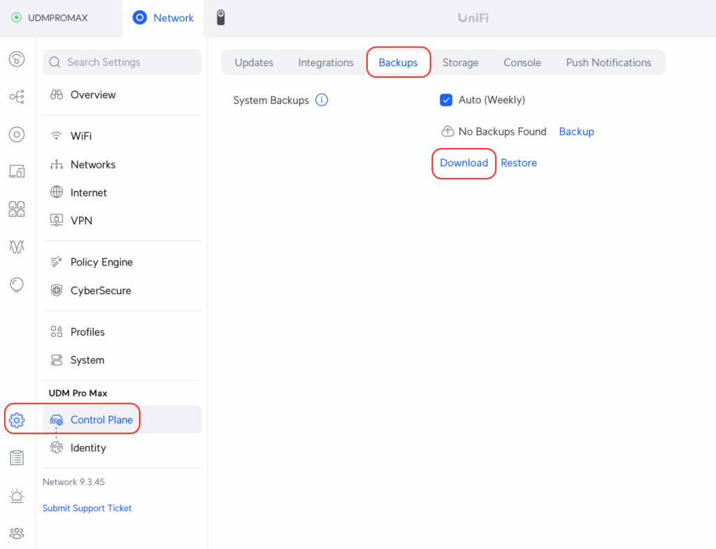
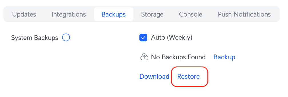
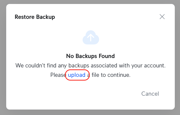
Upload the previously downloaded backup file and do a restore
Step 8: I then proceed to restore from the backup file that I previously copied on to my laptop. This took about 10 to 15 minutes;
The dialog is pretty cryptic, so be sure to click on the upload link and ignore the No Backups Found message.
Step 9: Once the system is up, I attached all the networking devices to the new Max and waited to ensure that all the Unifi devices are recognized by the new Max;
Step 10: I did one final reboot just to be sure that everything is okay;
So far so good. We did find a couple of issues. Rogers, my ISP provisioned a new WAN IP so I had to update my DNS entries. The VPN server configurations had to be updated with the new WAN IP.
I am going to let the Max run for a few days, and then perform a factory reset with the old Pro. We will then use the Pro as a Shadow (Hot Standby) Gateway for potential fail-over.
Today, I found it strange that with a clear, blue, sunny sky, our solar generation is half of what I expected. I then noticed that one of our two SolarEdge inverters was showing a fault.
In the past, when I got hold of a video that has hdmv_pgs_subtitle subtitle streams, I have always ignored it. Instead I tried to find a compatible subtitle in .srt format on the opensubtitles.org website. Today I came across a video that I am trying to archive that does not have the appropriate subtitles that I wanted. All of this would not have been an issue if my preferred mp4 format actually supports the hdmv_pgs_subtitle format.
I know an OCR (Optical Character Recognition) technique for extracting the subtitles from the hdmv_pgs_subtitle stream, but I am always in a hurry. This time, I bit the bullet and went down on this path.
Below are the steps that I had to go through.
First I had to download and install ffmpeg and mkvtoolnix packages on my Linux machine, and then execute the following commands to extract the Chinese subtitles that I wanted.
After the above commands, I will have mysub.idx and mysub.sup files. The first are the time index codes and the latter are the subtitle images.
On a Windows virtual machine, I had to download Subtitle Edit, a subtitle editor tool that has the OCR functionality, and convert the mysub.idx and mysub.sup into mysub.srt, which I can then later use to re-incorporate back into the archive video file.
After the OCR is completed.
Above is a screenshot of the application after the OCR is completed. I found that the engine mode of Tesseract + LSTM worked the best. Of course, I had to select the matching language that is befitting of the subtitle. Once I saved the finished product as mysub.srt I can then use this file to create archive.mp4 using ffmpeg.
Instead of using the Windows version of Subtitle Edit, we can use a command line version of vobsubocr. This is better for batch based processing. I installed vobsubocr on my NAS Ubuntu server with:
# Install OS dependencies
sudo apt update
sudo apt install build-essential cmake libtesseract-dev tesseract-ocr-eng libtiff5-dev tesseract-ocr-chi-sim

# First install Rust
curl --proto '=https' --tlsv1.2 -sSf https://sh.rustup.rs | sh

# We had to install from git
cargo install --git https://github.com/elizagamedev/vobsubocr

# Convert the *.idx and *.sub into srt
# Be sure file.sub is in the same directory as file.idx
vobsubocr -l eng -o output.srt file.idx