More than nine years ago, I created a remote garage door opener that connected to my HomeKit setup. This has proven to be a budget-friendly and super handy device, as I am able to control my garage door from anywhere in the world. I came up with this solution before WiFi-based remote garage door openers were commercialized.
However, recently the Raspberry Pi Zero W started to randomly lose WiFi network connection, and I have to reboot it all the time. Of course, this is very frustrating. Since the device is plugged into a ceiling plug, the same socket that is used for the actual garage door opener, it is quite inconvenient to cycle the device. I typically had to restart the whole garage by resetting the breaker on the main electrical panel.
I have some extra ESP32-S3 SuperMini boards on the side that I was going to replace the PiZero W with. I bought these from Pinduoduo (拼多多) when I was in China last year. Due to my laziness, I did not get around to it. Something else happened that allowed me to find another workaround.
About three and a half years ago, I purchased the VOCOlinc HomeKit Smart Plugs from Amazon. I used these to remotely control some fans in the house. One of these was recently freed up. I can then plug the adapter used to power the Pi Zero into the Smart Plug. Now I have a remote way to remotely power cycle the Pi Zero. A remote device to control the power of another remote device! Not only can I cycle the Pi Zero remotely, I can also programmatically determine when to cycle the device.
The Smart Plug is setup with my HomeKit environment and I recently learned that on a Mac, you can use the Shortcut App to toggle an accessory or scene with HomeKit.
I also found out that once I have a Shortcut, I can invoke it using the shortcuts command line command.
Using this shortcut concept, I can create a periodic cron job that effectively check the connectivity of the Pi Zero every 15 minutes. If I am unable to connect, I can effectively remote restart the Pi Zero. The script is listed below:
#!/usr/bin/env zsh
#
# This script is meant to be run as root

logger "cyclePizero.sh: INFO test connectivity to pizero.localdomain"
if ! ping -q -c 1 pizero.localdomain >/dev/null; then
        logger "cyclePizero.sh: ERROR unable to ping pizero.localdomain"
        logger "cyclePizero.sh: INFO restarting the resolved daemon"
        systemctl restart systemd-resolved.service
        logger "cyclePizero.sh: INFO cycling pizero.localdomain"
        ssh bigbird -n 'shortcuts run "Toggle Garage Opener"'
        sleep 3
        ssh bigbird -n 'shortcuts run "Toggle Garage Opener"'
        logger "cyclePizero.sh: INFO cycling completed"
else
        logger "cyclePizero.sh: INFO pizero.localdomain ping successfully"
fi
Note that I also sometimes have to restart the name resolution service, system-resolved. This is another reason sometimes HomeKit fails to communicate with the Pi Zero.
Hopefully this patch will work until I finally have time to replace it with the ESP32.
Our media server has reached 89% utilization and needs storage expansion. The storage makeup on the server uses Logical Volume Manager (LVM) and software RAID called mdadm. I can expand the storage by swapping out the hard drives with the least capacity with new hard drives with a larger capacity like I have previously done.
I thought I try something different this time around. I would like to switch from LVM to ZFS, an LVM alternative that is very popular with modern mass storage systems, especially with TrueNAS.
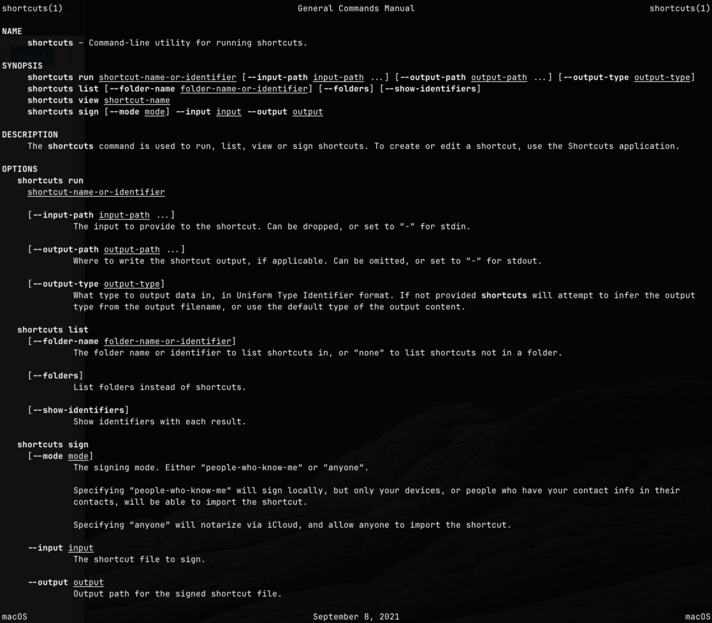
All filled with 8 drives
Before I can attempt the conversion, I will first need to backup all of the content from the media server. The second issue is that I needed more physical expansion space on the server to house more hard drives. The existing housings are all filled except for a single slot, which is going to be insufficient.
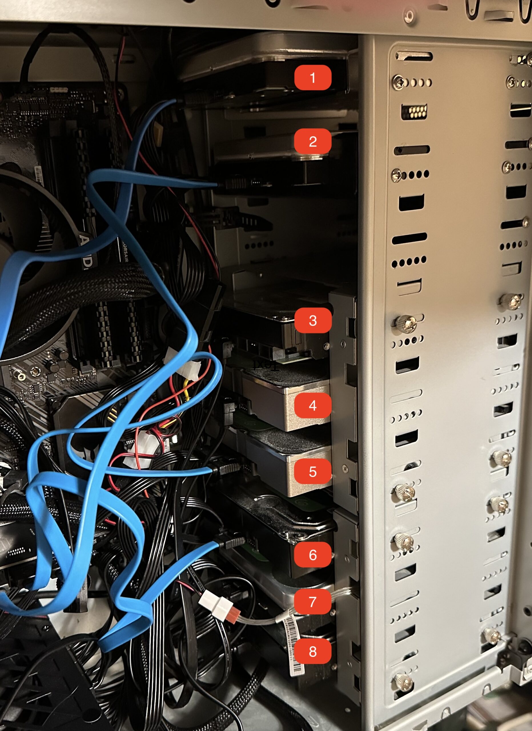
A related issue is that I no longer have any free SATA slots available for the new hard drives, so I purchased GLOTRENDS SA3116J PCIe SATA Adapter Card with 16 SATA Ports. Once this is installed, I have more than enough SATA ports for additional storage.
PCIe SATA Card Installed
One downside of the SATA card is that it is limited to PCIe 3.0 x1 speed. This means data transfer is limited to a theoretical maximum of 1GB/s. Given that the physical hard drives top out at 200MB/s, I don’t think we need to be too concerned about this bottleneck. We will see in terms of practical usage in the future.
I am so lucky to have extra SATA power cables and extension cables laying around and my 850W existing power supply has ample power for the additional hard drives.
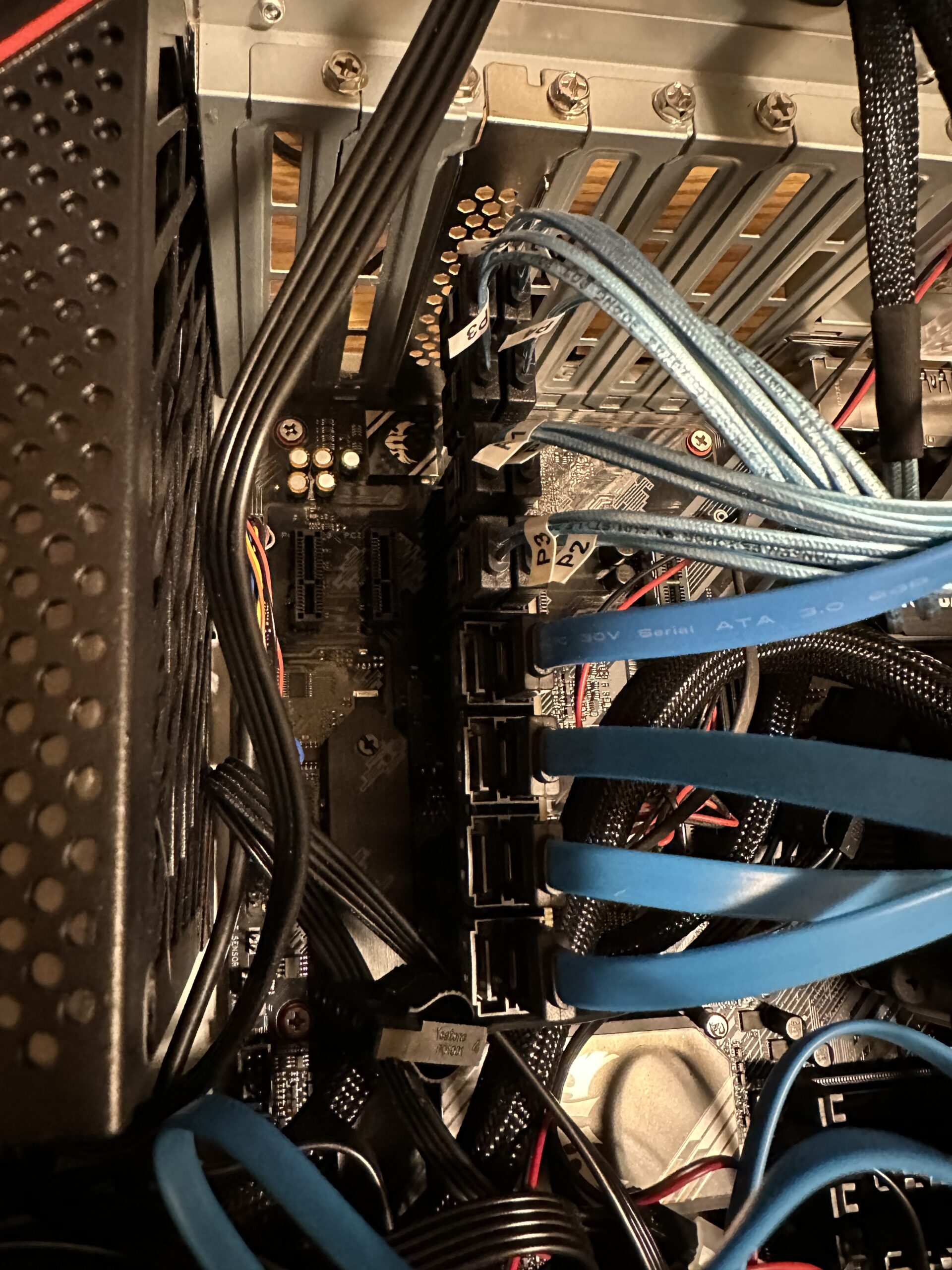
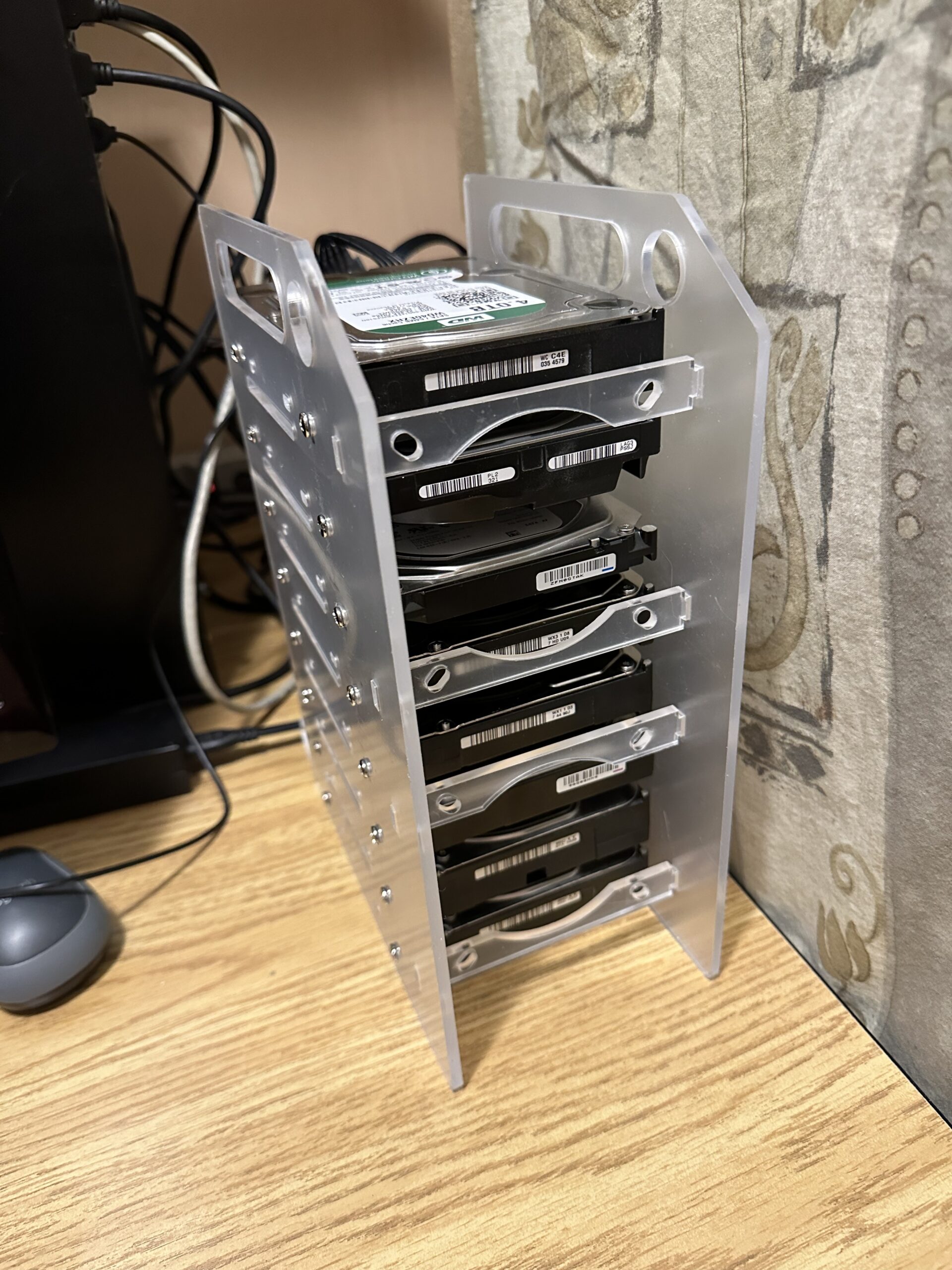
How do we store the additional hard drives with a full cabinet? I went to Amazon again and purchased a hard drive cage, Jaquiain 3.5 Inch HDD Hard Drive Cage 8X3.5 Inch HDD Cage. I did not have to buy any new hard drives yet, because I had plenty of old hard drives laying around. After I put together the cage with 8 really old and used hard drives, it looks something like this:
With this new additional storage, I am now able to backup the media content from my media server. However, before I do that there is one last thing that I need to do, and that is to experiment with an optimal ZFS pool configuration that will work with my content and usage. I will perform this experimentation with the additional storage before reconfiguring the old storage with ZFS. Please stay tuned for my findings.
After booting the system with 16 hard drives, I measured the power usage and it was hovering around 180W. This is not too bad, less than 2 traditional incandescent light bulbs.
Addendum:
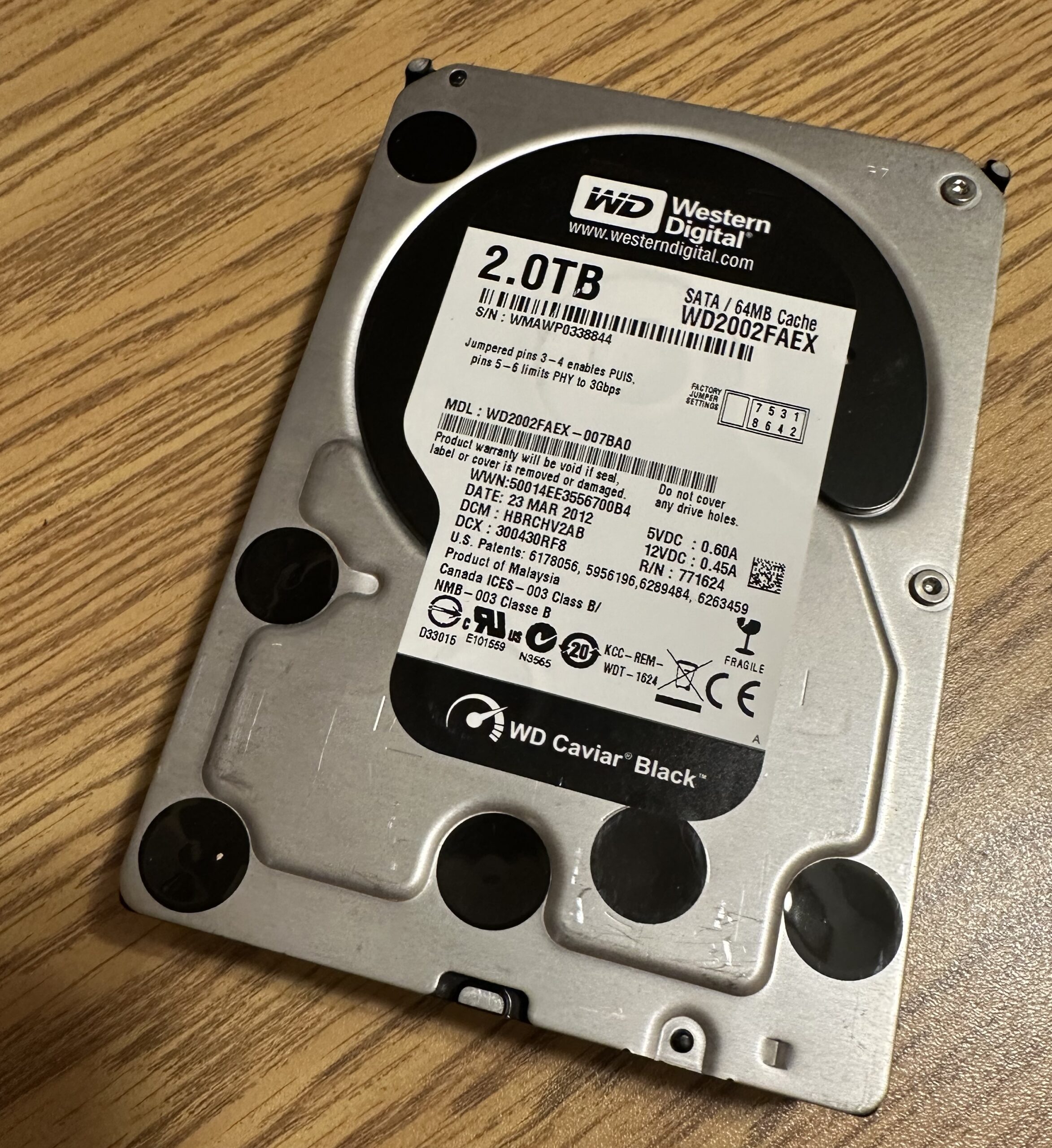
During my setup, I had to spend hours deciphering an issue. My system did not recognize my old hard drives. After many trials, I finally narrowed down that the GLOTRENDS card is not compatible with an old 2TB Western Digital Enterprise Drive. This is the first time that I came across SATA incompatibilities.
There is another possibility that these drives were damaged by the usage of an incorrect modular power cable. I found that these drives also do not work with my USB3.0 HDD external dock as well. This gives additional credence that the physical drive has been damaged.
The troubled drive with the SATA card
All my other drives worked fine with the card.
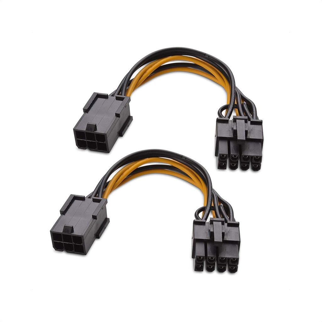
Another discovery is that not all modular power cables will work with my ASUS ROG STRIX 850W power supply. Initially, I thought I would use an 8-pin PCIe to 6-pin adapter along with a 6-pin to SATA power cable designed for Corsair power supplies.
PCIe Power Adapter from Amazon
OwlTree PCI-e 6 Pin Male to 4 SATA 1 to 4 SATA Female Power Supply Splitter Supply Cable for Corsair Modular RM650X RM750X RM850X RM1000X
Using the above cables will cause the power supply not to start. I had to hunt for the original cables that came with the STRIX power supply.
Learned a lot from rejigging this media server. My reward is to see my server boot up with 16 hard drives and 2 NVMe SSD drives recognized. I have never built a system with so many drives and storage before.
Our home Network Attached Storage (NAS) media server is going below 4 Terabytes of free space. The Seagate IronWolf 12TB hard drives were on sale with Amazon offering them below $300. I figure that I swap out two old 6TB drives with these new 12TB drives resulting in a net increase of a further 6TB of storage.
The last time this was done was around two years ago when I replaced 4TB and 6TB hard drives with 10TB hard drives.
So far the mdadm and LVM storage architecture has proven to be very flexible. I am able to mix drives of different sizes and able to grow our media storage volume over time.
Previously I had to make two swaps, each swap for each drive in the array. Effectively I am changing two 6TB drives for two 12TB drives because they are in a Raid 1 array. I cannot swap both at the same time, because I have to incrementally sync the data from the old drives to the new ones.
This has always been inconvenient because it means opening the physical server twice. However, this time I used my USB 3.0 HDD dock. I inserted one of two 12TB new drives into the dock, and then I temporarily created a three disks Raid 1 array. Once the sync is completed, which took 10+ hours, I remove one 6TB drive from the array configuration and I then physically replace both 6TB drives with both 12TB new drives in the server chassis, and place one old 6TB drive into the dock. The 6TB drive in the dock is the one that is still in the array configuration. I then add the second 12TB drive that is already in the server chassis to the three disk array. Once again, a sync is required to accommodate the second 12TB drive. This also took 10+ hours. Once the second sync is completed, I can finally remove the second 6TB drive in the dock from the array and have the array returned back to a two disk Raid 1 array.
The above description is probably quite confusing, but this technique allowed me to just have a single down time for the server instead of two when swapping hard drives in the server chassis.
There will be an additional downtime when I grow or resize the LVM volume and file system.
After this upgrade I should have the following Raid 1 (fully mirrored) arrays:
An array with 2 x 8TB
An array with 2 x 10TB
An array with 2 x 10TB
An array with 2 x 12TB
The above four arrays are combined into a logical volume using LVM that results in a total volume size of 40TB (fully mirrored) or a little over 36TiB of usable space (increasing from the old 31TiB).
This is an update to my Sunroom Project that I detailed in a previous post.
After the installation of the solar panels, there was a question of whether the solar panels had enough juice to keep the batteries charge for cloudy days or night time operations. After a few days of operation, the observation is a definitive “no”.
The overall load of water pumps, fans, and temperature sensors amounted to be about 80W. The two solar panels (100W each, equaling 200W) during sunny days will only yield enough to cover this load. The less than optimal positioning on the sunroom’s roof will deprive the solar panels in operating in their optimal efficiency. Even on a really sunny day the panels may have a little surplus to give back to the battery, but nothing close to offer a continuous charge to the battery. Most of the time, the solar power is just enough to power the load and leave the battery as is. Left unattended, the batteries will slowly drain to nothing, as it is being discharged during cloudy days and at night times.
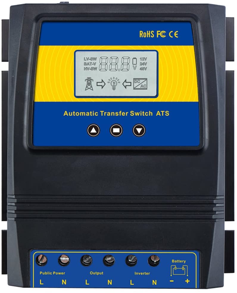
Automatic Transfer Switch from Amazon
So much for going entirely off grid! Since it is a sunroom, the roof based real estate is a bit precious, and two panels is as much as we wanted to take away from the sunshine that feed the plants. Not all bad news, we still have the opportunity to time shift our power needs from the grid, from peak time to non-peak time.
For the past few days, I had to go out to the sunroom during the evenings and switch the battery from solar power and back to the grid via the 480W DC Power Supply, so that it will charge itself back during the night. This is of course super inconvenient. What I needed is an Automatic Transfer Switch (ATS). Something like the one shown on the left offered by Amazon.
The price was pretty exorbitant, over $150.00, much more than what I wanted to spend. When there is a need, there is an opportunity to invent. I thought this is such a good opportunity to create my own ATS.
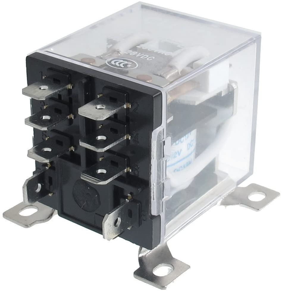
My ATS will be a simple 12V relay powered by the battery itself, and controlled by a WiFi capable microcontroller like the ESP32S that is perfect for the job. With a bit of searching on Amazon, I found this gem, a simple 12V relay that is only around $16.
URBEST 8 Pin JQX-12F 2Z DC 12V 30A DPDT
At most, the relay only needed to handle 10A, so the 30A rating is a total overkill, but good enough for my purpose.
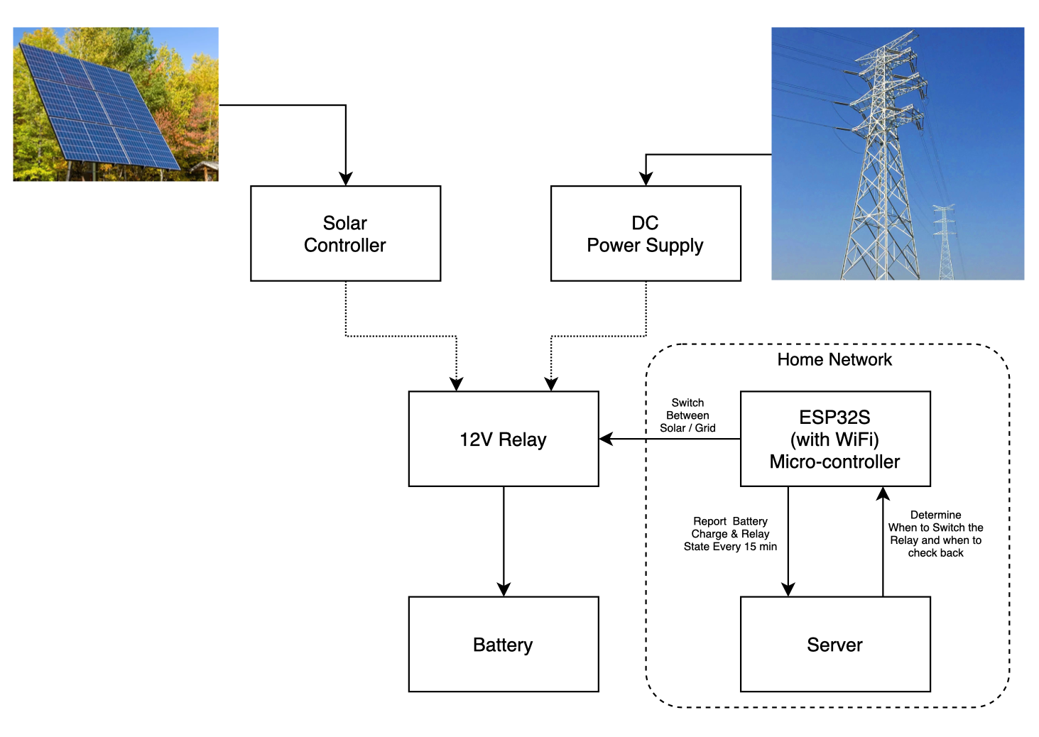
I already have an ESP32S that I purchased earlier from AliExpress or Ebay. This is a WiFi enabled micro controller that can be programmed with the popular Arduino IDE. They were less than $5 a piece when I got them, and was literally sitting on my shelf awaiting for a project such as this. The master plan is as follows:
click to enlarge
The EPS32S will remotely control the relay, which physically makes contact between the battery with either of the solar controller or the power supply. The when is determined by a remote server on the same home network. The ESP32S will periodically post the battery voltage status and the current state of the relay to the server.
Using this approach, I can place the majority of the smarts on the server instead of the micro controller. I can also change the logic without having to reprogram the ESP32S.
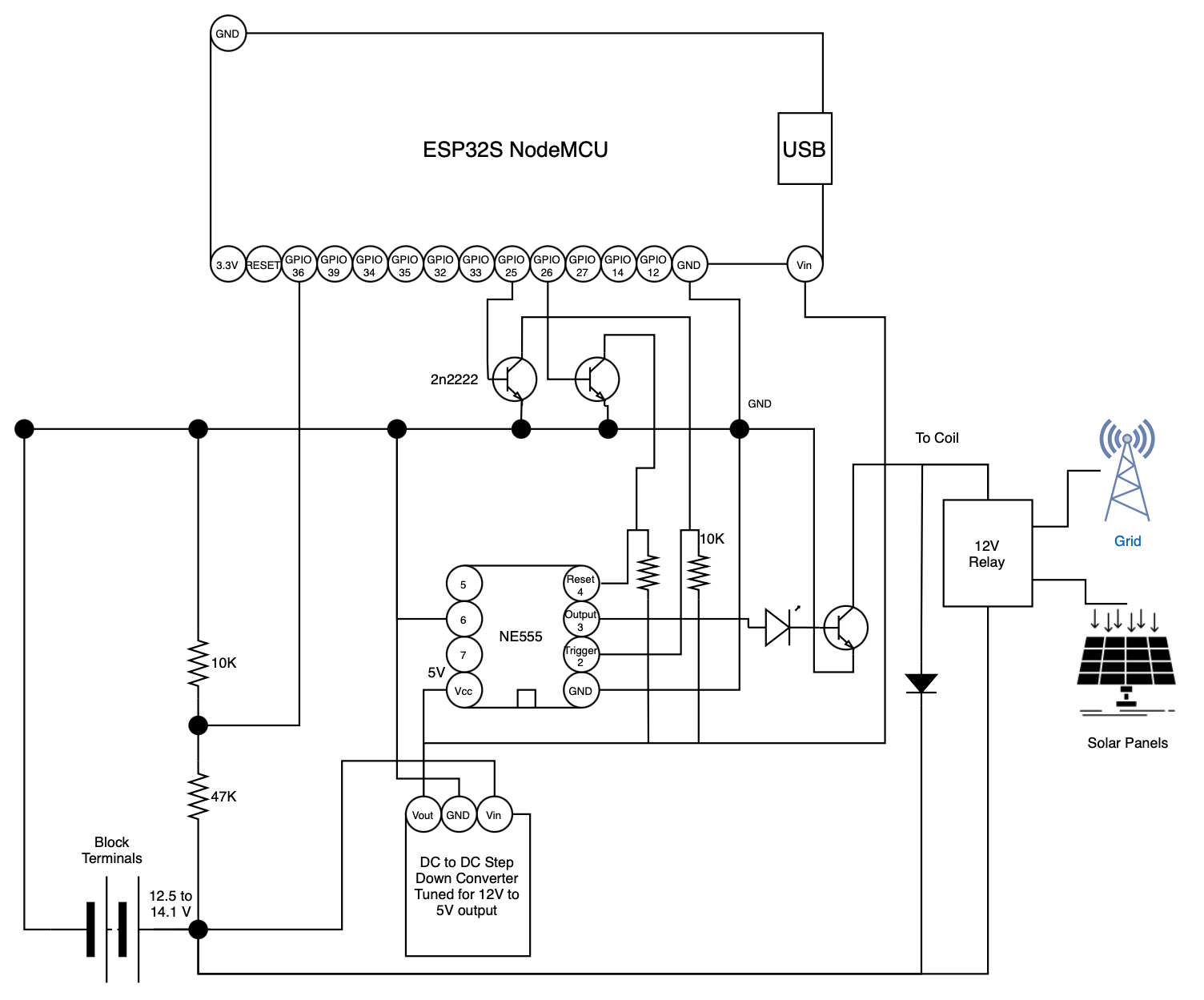
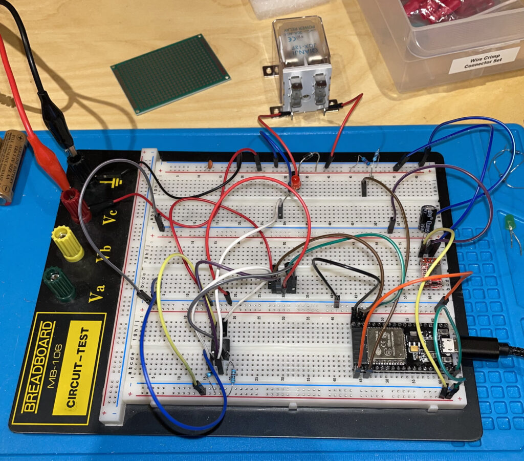
The ESP32S comes with many GPIO pins. We will make use of three of the GPIO pins, one to detect battery voltage via a voltage divider. The other two will send a pulse to a simple latch that will drive the switch position of the relay. The latch will use a popular NE555 chip in bistable mode. Here is a simple schematic that I put together.
click to enlarge
I prototyped the above circuit on a breadboard and using a desktop power supply to simulate the battery.
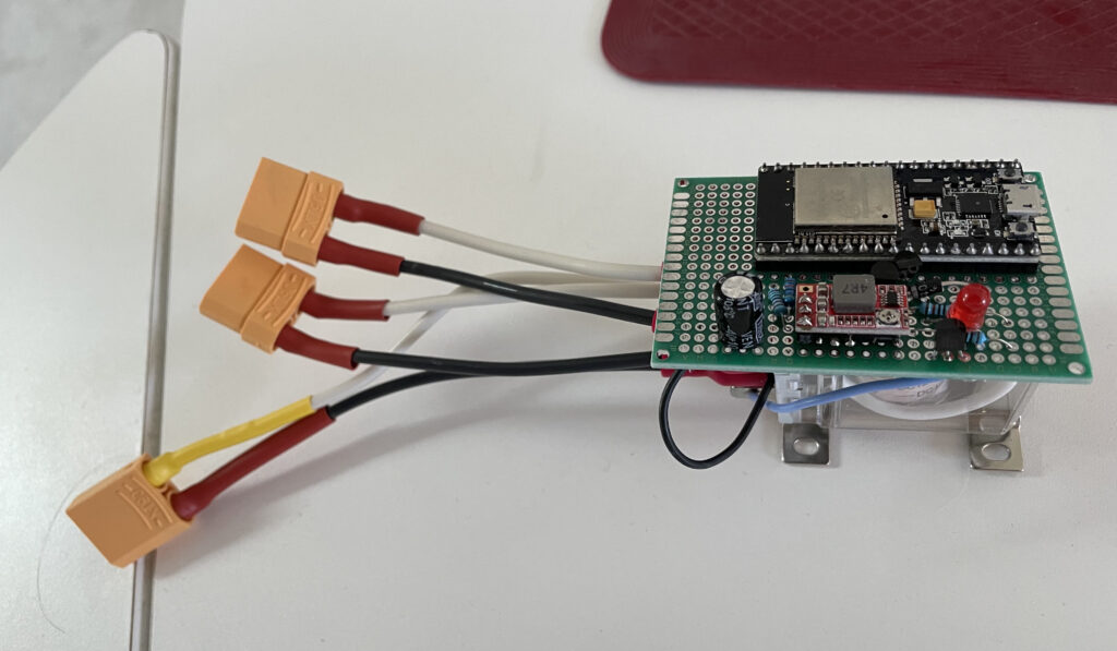
Everything worked as expected, and I proceeded to solder everything up on a PCB.
Below is the Arduino sketch that I wrote for the ESP32S to report the battery voltage and the relay switch state to my server.
#include <WiFi.h>
#include <HTTPClient.h>

/* Server and WiFi configurations are fake */

#define SERVER_IP "192.168.1.5"

#ifndef STASSID
#define STASSID "##############-iot"
#define STAPSK  "##################"
#endif

#define uS_TO_S_FACTOR 1000000

#define BATT_VOLTAGE_GPIO 36
#define GRID_PULSE_GPIO 25
#define SOLAR_PULSE_GPIO 26

float volt = -1.0;
RTC_DATA_ATTR int currentState = -1;

void setup() {

    pinMode(BATT_VOLTAGE_GPIO, INPUT);
    pinMode(GRID_PULSE_GPIO, OUTPUT);
    pinMode(SOLAR_PULSE_GPIO, OUTPUT);

    digitalWrite(GRID_PULSE_GPIO, LOW);
    digitalWrite(SOLAR_PULSE_GPIO, LOW);

    Serial.begin(115200);

    Serial.printf("Connecting to %s..\n", STASSID);

    WiFi.begin(STASSID, STAPSK);
    while (WiFi.status() != WL_CONNECTED) {
        delay(250);
        Serial.print(".");
    }

    Serial.print("\nConnected with IP: ");
    Serial.println(WiFi.localIP());
}

void pulse(int pin) {
    digitalWrite(pin, HIGH);
    delay(200);
    digitalWrite(pin, LOW);
}

// the loop function runs over and over again forever
void loop() {

    WiFiClient client;
    HTTPClient http;

    digitalWrite(LED_BUILTIN, HIGH);

    float v = 0;
    for (int i = 0; i < 200; i++) {
        v += analogRead(BATT_VOLTAGE_GPIO);
        delay(2);
    }
    volt = v / 200.0;

    Serial.print("Voltage Read: ");
    Serial.println(volt);

    http.begin(client, "http://" SERVER_IP "/autoTransferSwitch.php"); //HTTP
    http.addHeader("Content-Type", "application/x-www-form-urlencoded");

    // start connection and send HTTP header and body
    String postStr = "id=sunroom";
    postStr += "&volt=" + String(volt);
    postStr += "&state=" + String(currentState);

    int httpResponseCode = http.POST(postStr);
    digitalWrite(LED_BUILTIN, LOW);

    Serial.printf("Response code: %d\nResult: ", httpResponseCode);

    String instructions = http.getString();
    Serial.println(instructions);

    String result = "nothing";
    long sleepTime = 5L;

    char buffer[100];
    strncpy(buffer, instructions.c_str(), 100);

    const char d[2] = ",";
    int field = 0;
    char* token = strtok(buffer, d);
    while ( token != NULL ) {
        if (field == 0) {
            result = String(token);
        }

        if (field == 1) {
            sleepTime = atol(token);
        }
        token = strtok(NULL, d);
        field++;
    }

    if (result.equals("solar")) {
        pulse(SOLAR_PULSE_GPIO);
        currentState = 1;
    } else if (result.equals("grid")) {
        pulse(GRID_PULSE_GPIO);
        currentState = 0;
    } else {
        digitalWrite(GRID_PULSE_GPIO, LOW);
        digitalWrite(SOLAR_PULSE_GPIO, LOW);
    }

    http.end();

    Serial.print("Sleeping for seconds: ");
    Serial.println(sleepTime);

    esp_sleep_enable_timer_wakeup(uS_TO_S_FACTOR * sleepTime);
    esp_deep_sleep_start();
}
One nice thing about the ESP32S is its ability to go into a deep sleep where it can keep its state with almost zero power. This way, the micro controller doesn’t act as a power sink for the entire system. I took advantage of this feature, so that the server can also tell the ESP32S how long it should sleep.
On the server side, I have a simple PHP script that will take into account time of day, and the current battery charge.
<?php

date_default_timezone_set('America/Toronto');

// I've changed the location to protect my own privacy

$lat    = 42.9293;
$log    = -102.9478;
$zenith = 90;

$nextWait = 900;

// The voltage levels are ADC readings from ESP32 (divided by 10) and not actual volts

// voltage level when battery is fully charged and can either be used or be charged with solar
$solarChargeLevel = 280;

// voltage level when battery is okay to be used with or without solar (come off of grid)
$okChargeLevel    = 260;

// voltage level when battery must be charged (get on grid)
$mustChargeLevel  = 252;

$now = time();

$sr = date_sunrise($now, SUNFUNCS_RET_TIMESTAMP, $lat, $log, $zenith);
$ss = date_sunset($now, SUNFUNCS_RET_TIMESTAMP, $lat, $log, $zenith);

$srStr = date("D M d Y - h:i:s", $sr);
$ssStr = date("D M d Y - h:i:s", $ss);

$logFile = "/home/kang/log/autoTransferSwitch.log";
$dateStr = date("Y-m-d H:i:s");

header("Content-Type: text/plain");

$id      = isset($_POST["id"]) ? $_POST["id"] : null;
$batVolt = isset($_POST["volt"]) ? $_POST["volt"] : null;

// -1 = initial, 0 = grid state, 1 = solar state
$currentState = isset($_POST["state"]) ? intval($_POST["state"]) : -1;

file_put_contents($logFile, "$dateStr, " .
    "device reported: battery voltage: $batVolt and current state: $currentState\n",
    FILE_APPEND);

if (!is_null($id)) {

    if ($id === "sunroom") {
        $action = "nothing";
        $b      = intval($batVolt) / 10.0;

        // During day is defined by one hour after sunrise and one hour after sunset
        $duringDay   = (($sr + 3600) <= $now && $now <= ($ss - 3600));
        $duringNight = (!$duringDay);

        if ($currentState == -1) {
            if ($b <= $mustChargeLevel) {
                $action       = "grid";
                $currentState = 0;
            } else {
                $action       = "solar";
                $currentState = 1;
            }
        } else if ($currentState == 0) {

            // We are charging from the grid

            if ($duringDay && $b >= $okChargeLevel) {

                // During the day we want to use solar or the battery as much as possible;
                // This is a trickle charge so that we can take advantage of the sun.

                $action       = "solar";
                $currentState = 1;

            } else {

                // Otherwise charge until battery is full

                if ($b >= $solarChargeLevel) {
                    $action       = "solar";
                    $currentState = 1;
                }

            }

            if ($b >= 0.985 * $solarChargeLevel) {
                // We are getting closer to fully charge so
                // reduce communication interval from 15 min to 5 min
                $nextWait = 300;
            }

        } else if ($currentState == 1) {

            // We are either using the battery or the solar panels

            if ($b <= $mustChargeLevel || $now > $ss + 3600) {

                // Charge the batteries if we must or one hour past sunset

                $action       = "grid";
                $currentState = 0;
            }

            if ($b <= 1.025 * $mustChargeLevel) {
                // We are getting closer to require charging so reduce
                // communication interval from 15 min to 5 min
                $nextWait = 300;
            }

        }

        // for testing purpose
        // $nextWait = 15;
        echo ($action . "," . $nextWait);

        file_put_contents($logFile, "$dateStr, $batVolt, $action, " .
            "sun: [$srStr - $ssStr], new state: $currentState, wait: $nextWait\n",
            FILE_APPEND);
    }

}
The above state transition logic is pretty simple to follow so I am not going to explain it in depth here. There are a couple of features that I like to expand on.
By default, the sleep time is 15 minutes, but the server will shortened it to a shorter interval of 5 minutes when the battery is near empty or full. This sample frequency should be enough for the server to make the appropriate switching decision. Once a switch in the relay has occurred, the sleep time can be reverted back to 15 minutes. For debugging purposes, I can also change the server script to a very fast sample rate of every 15 seconds.
The other feature is the account of day and night time. This first version of the algorithm will attempt to use solar and/or battery during the day, and only charge from the grid when it is absolutely necessary. If we do charge from the grid during the day, we don’t need to fill it up, but only charge it to a level that can be used again. We will then attempt to top up the battery about 1 hour after sunset.
My ATS is now installed and operating for an entire day, so far so good and I don’t have to go into the sunroom any more to perform a manual switch. The algorithm can be further enhanced by getting additional readings from the solar controller, but I didn’t want to go through the trouble. I think what I have so far should be sophisticated enough. We’ll see.
2021-06-18 Update: After several days of operation, I noticed that the ATS, more specifically the ESP32 micro-controller hangs or fails to wake from deep sleep after a few hours of operation. Upon further investigation, it may be a combination of unstable supply voltage (from the battery), memory leaks of the standard WiFi libraries or the usage of String types. I am not sure. I had to re-write my ESP32 Arduino sketch to include a watch dog reset as well as perform a timed, software triggered hardware reset of the controller itself every 30 minutes or so. I also eliminated the deep sleep functionality and simply resorting to delays and resets. It has been running for about a week without any hiccups.
YouTube viewing has been one of our favourite pass times during the lock down nature of the Covid-19 pandemic. I personally have been watching quite a few channels on how to use LiPO4 cells to build rechargeable battery banks for solar applications, primarily for off grid purposes.
We have a sunroom in our back yard that we used during the summer to grow some vegetables. It has some electrical needs such as water pumps, a temperature sensor, and a fan. Currently there is an electrical socket, fed from the house, that we plug these devices into. We thought it would be a good project to try to get our sunroom off grid. This would be a good learning project.
The first task is to build a 12V LiFePO4 prismatic cells battery bank. I purchased 4 3.2V 100Ah battery cells from AliExpress. The cells came with bus bars so I did not have to purchase those. However, I did have to buy a battery management system (BMS) to balance and manage the charging and discharging of the battery cells. It was very tempting to buy a BMS from AliExpress, but I decided to be cautious and purchased one from a US vendor with the accompanying and preferred quality control. The company Overkill provides a 12V BMS specifically for four LiFePO4 battery cells in series.
It took a very long time for the batteries to arrive from China. I suppose the pandemic could be one of the many reasons for the delay. Once they arrived, I connected in parallel and proceeded to perform a top balance procedure with my voltage limiting desktop power supply. This step is required because each cell will have a different voltage potential from each other. We want all the cells to have the same voltage potential to maximize the capacity that we will get from the aggregated 12V battery bank.
Cells in parallel being topped balanced at 3.65V until zero current
To top balance all the cells, first I hook up the cells in parallel and charge them at a constant voltage of 3.65V. The charge will continue until my desktop power supply shows zero amp going into the battery. This process took a very long time, almost 2 days.
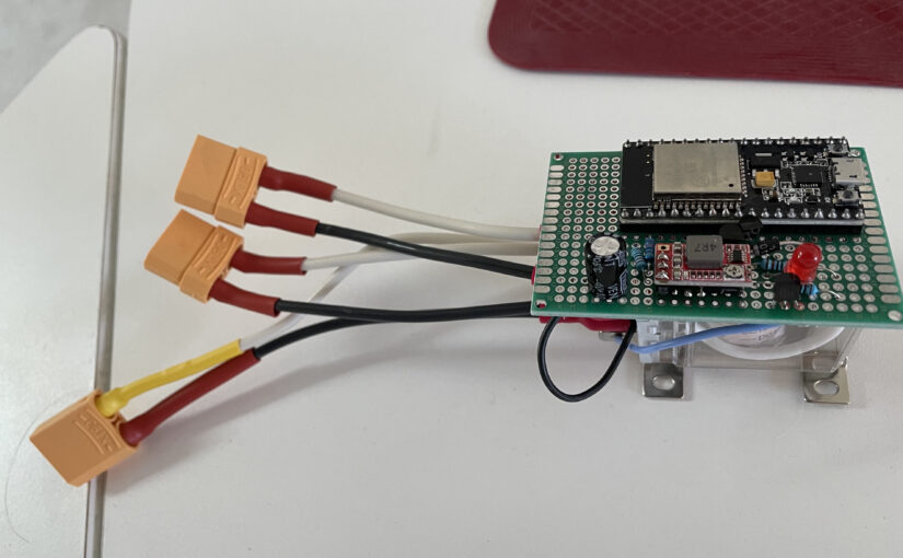
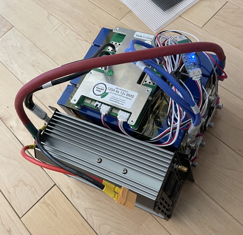
Once the cells are balanced, I reconfigured the cells in series and proceeded to hookup the BMS and the pure sine wave 600W inverter I purchased from Amazon. I had to buy 4 AWG wire, once again from Amazon, because the 10 AWG wire that I purchased earlier was not going to be enough if I want to discharge the battery at 600W which is going to result in more than 50A of current at 12V. I used the remaining 10 AWG wire for solar controller and panel hookups. I also got some XT90 connectors so that I can easily plug/unplug the solar charge controller, solar panels, and potentially plugin charger. I will talk about the solar side some more later on.
All wired up. The yellow XT90 connector is to either a solar charge controller or an external DC charger
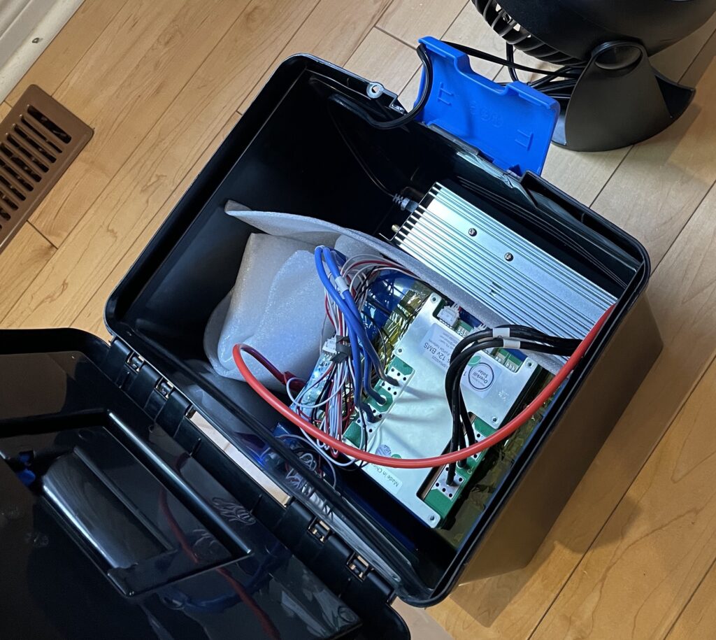
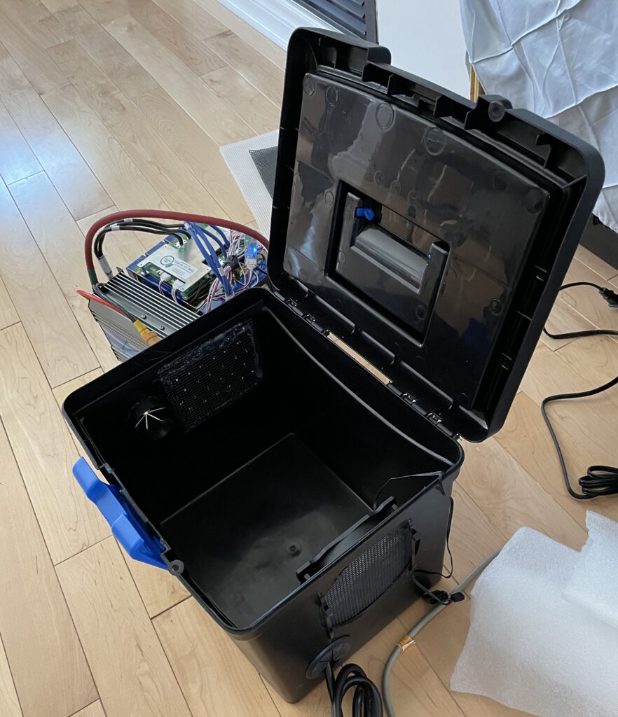
So now that we have the guts of our 12V LiFePO4 battery pack, we need to find a suitable home for this thing. My wife had an extra plastic filing box hanging around which is perfect for this.
A filing box is perfect to fit everything
Custom grommets and added a PC fan
I needed to drill some holes to fit a 12V 120mm PC fan for ventilation, and a couple of 2″ grommets so that we can pass plugs and connectors through the box. The fan will be powered by the inverter.
At this point we have ourselves a 1200Wh portable super battery pack that can power up to 600W of electronics, which will be great for road trips. If you plug a 20W iPhone fast charger and charge your phone, it can continuously charge for 60 hours (2.5 days). That is a lot of phones. If your MacBook Air ran out of juice on the road, then this battery pack can power a 45W charger for your MacBook Air for more than a day, and also charge your computer fully. Quite a handy thing to have for emergencies.
Doubles as a 1200Wh portable battery bank
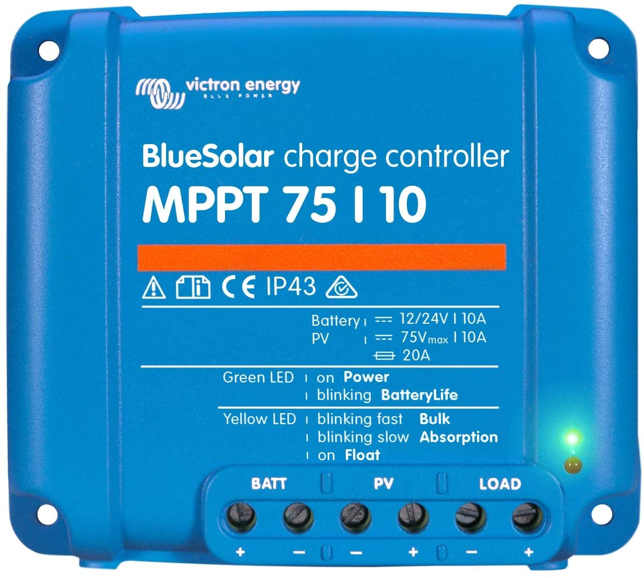
For the solar panels, I purchased two Xinpuguang 100 W flexible solar panels from Aliexpress. They were about $1 / Watt, a pretty good deal. I hook the two panels together in series and got a Victron BlueSolar MPPT 75/10 solar charger to manage the charging of the batteries. The charge controller can accept a maximum of 75V and outputs a maximum of 10A.
The charge controller will automatically adjust the amperage and voltage to the battery bank as required ensuring optimal charging scenario. During a sunny day, it will run the sunroom load from the panels and any remaining current will goto charge the battery. At night, the battery will run the sunroom.
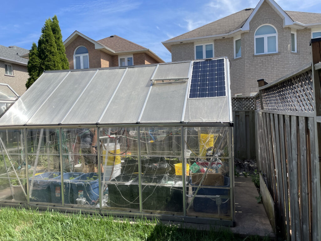
Today, we installed the entire setup. The battery is placed inside the green house to give it some precipitation protection.
The panels are latched to the roof of the green house, one on each side.
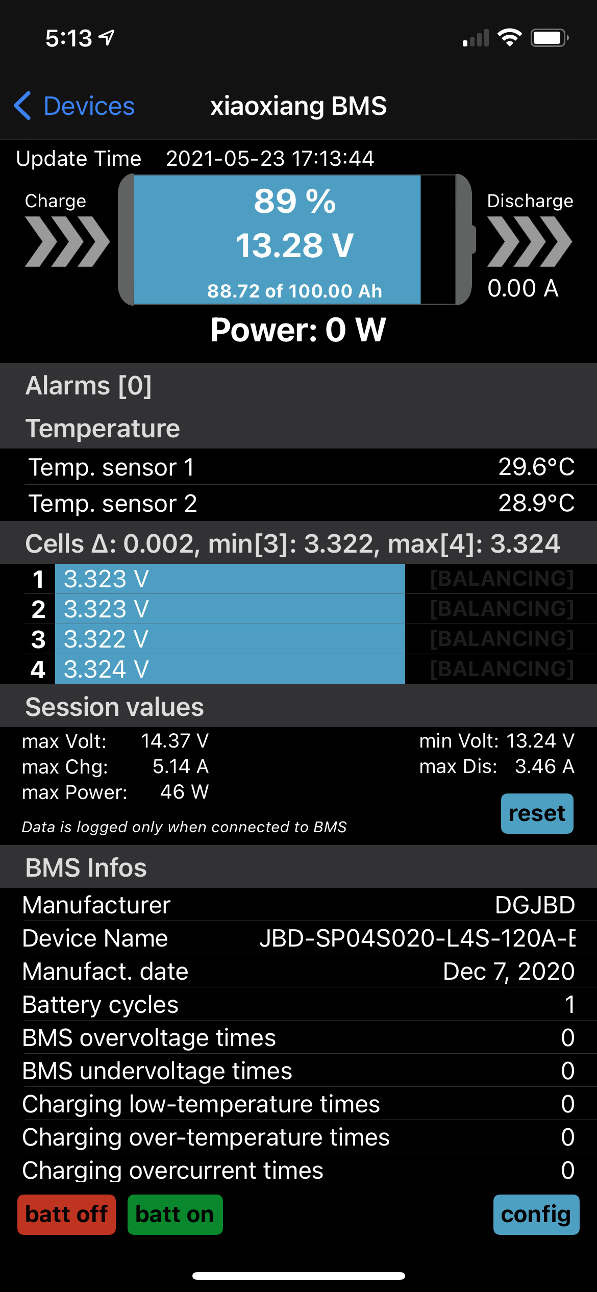
The BMS unit has a bluetooth connection and an iOS App. I can use my iPhone when in bluetooth range of the battery to see if the battery is being charged or discharged.
I took the following screen shot of the app today at around 5pm EDT. You can see that there is no current going into the battery and no current going out of the battery. This means the sun is powerful enough to run all the pumps and other electrical appliances in the sunroom. Pretty cool!
It is still too early to tell yet whether there is enough sun power to charge the battery and run the electrical devices in the sunroom in a sustainable manner. My current suspicion is that the two panels are just enough even on a full, bright, sunny day and at peak hours, to power devices and also provide surplus current to charge the batteries.
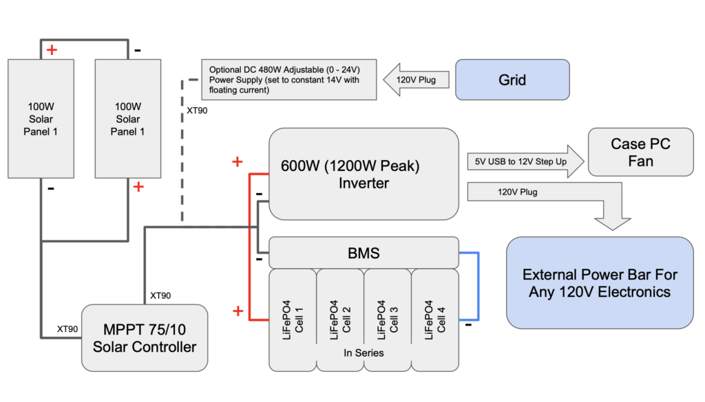
Here is my overall connectivity diagram:
We will let the system run for about a week to see if this is sustainable during the summer months or not. If not, then I will have to create an automatic transfer switch so that we can intermittently recharge the batteries during the evening with an optional 480W DC charger, which I also got from Aliexpress. This charger can operate between 0-24V and 0-20A. To charge the battery bank, I have set it to a constant voltage of 14.0V and allow the output current to flow unrestricted. This should charge the battery fully in a little over 4 hours from scratch.
Overall, I learned a lot from this project and what a great way to spend the pandemic indoors. This could be a precursor to a DIY Tesla Powerwall Project. We’ll see.
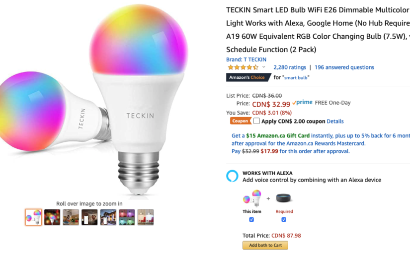
I found a pair of these on Amazon for around $30 CAD (after a $2 coupon saving). They look like fun to install. I figured that now that I know how to installed Tuya devices with the Homebridge, these would be great additions to the common areas of the house, should we need some colour added to our lives.
Amazon was extremely helpful and these bulbs came the next day. Amazon Prime is such a great service!
I proceeded to add these devices to the TuyaSmart app without any issues. Tested the lights using the app. I then logged into the Tuya developer site to ensure that the new devices were registered.
I provided the configuration into Homebridge using the following template from the homebridge-tuya-lan plugin page. Unfortunately, the provided sample template did not work, because the datapoint identifier, a terminology that represents a numerical id that uniquely identifies a specific device function, such as power on/off the device. My vague understanding is that the OEM, in this case Teckin, can pick and choose the datapoint identifier when creating their product, and map specific numerical values to the various functions of their devices. I gleaned this from Tuya’s developer documentation here.
Therefore, the provided sample of:
"dpPower": 1
was simply incorrect. The dpPower setting needs to have the correct numerical value that points to the power on/off functionality of the device. The default of 1 was not working, and I now have the challenge of finding the right value.
Through much research on Tuya’s site and Google, I found out that each device has a signature / schema. I found out that I can get the current status by executing the following command line (key and id has been replaced with fake ones):
I then guessed that the datapoint identifier started with 20 instead of 1. Also based on the value of 1000 for dps '22', I also deduced that I had to change the colorFunction from HEXHSB to HSB, because it was not using HEX to denote ranges. The last hint that I got was from this comment on a forum. Ultimately, consolidating all of the above knowledge, I arrived to the final configuration that looks like this:
The lights finally worked with Homebridge and therefore also worked with HomeKit. I thought adding these couple of bulbs would be done in a few minutes, but it took a little more effort than I thought.
I couldn’t be happier that they now work with Siri!
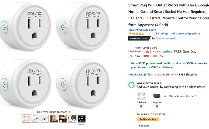
Recently I received an Amazon email, and I found the above Gosund Smart Socket promotion. Four smart plugs for $33 CAD. Unfortunately, it was not HomeKit compatible. I did not want to have any of my smart IoT devices connected to Amazon or Google so no thank you Alexa and Google Home.
A few years ago, I built my own smart garage door opener and hooked it up to the Homebridge server that is running on my NAS media server. The Homebridge server allows non-certified IoT devices to be connected to HomeKit. My garage door opener being one of them. I did a cursory search on Google and found that it should be possible to connect the Gosund outlets to HomeKit using Homebridge, so I took the plunge and made the purchase.
The plugs came and I downloaded the Gosund app and setup one of the outlet. It worked like a charm through the Gosund app. As I was setting up this single outlet with Homebridge, I found tuya-convert. This is an alternative to Homebridge. Instead of registering the device to Homebridge, tuya-convert claims that I can just flash the firmware and I can add the Gosund plug directly to HomeKit. Sounds attractive and I have to give it a shot. Long story short, I was successful with replacing the firmware, but when configuring the plug I provided wrong configuration data and as such I was locked out of the plug, effectively bricking the plug. Nothing ventured, nothing gained. While doing this exercise, I learned a lot about how to use esp-homekit-devices project to turn any ESP8266 chip set and make it HomeKit compatible. This could be very handy in a future project, but for now let’s go back to Homebridge.
I found that the version of homebridge on my NAS server was outdated, and so was the version of node. I backed up my existing homebridge configuration and proceed to uninstall homebridge.
I installed the latest stable version of node as of the writing of this blog, v12.19.0. I then followed these instructions and installed the latest version of Homebridge. This new version came with a web based UI as well. For convenience, this is what I did:
I then reinstalled the Homebridge plugins that I previously had, which included homebridge-camera-ffmpeg, and my custom homebridge-kl-garage.
The Gosund plugs effectively uses the Tuya IoT Platform. So instead of using the Gosund App, I downloaded the TuyaSmart App from the App Store. The user interface is nearly identical to the Gosund App and I re-added the outlet with the TuyaSmart App.
Now I’m ready to install the homebridge-tuya plugin using the instructions here:
As per the instructions, I watched the YouTube video and followed its steps using the QR-Code method.
However, I found the video to be incomplete and I ran into issues when running the tuya-cli command. Essentially I got an error indicating that I did not have permission to run the API.
Using the information I had from the video and after some more Google searches, here are the steps which I followed and they worked for me.
First, install the tuya-cli command:
sudo npm i @tuyapi/cli -g
Next I had to create an account with iot.tuya.com. The sign-up process was a bit tricky because their email sending out the verification code seem to be slower than the allotted 60 seconds before the whole process timeout. It took me a couple of tries before I was able to create an account.
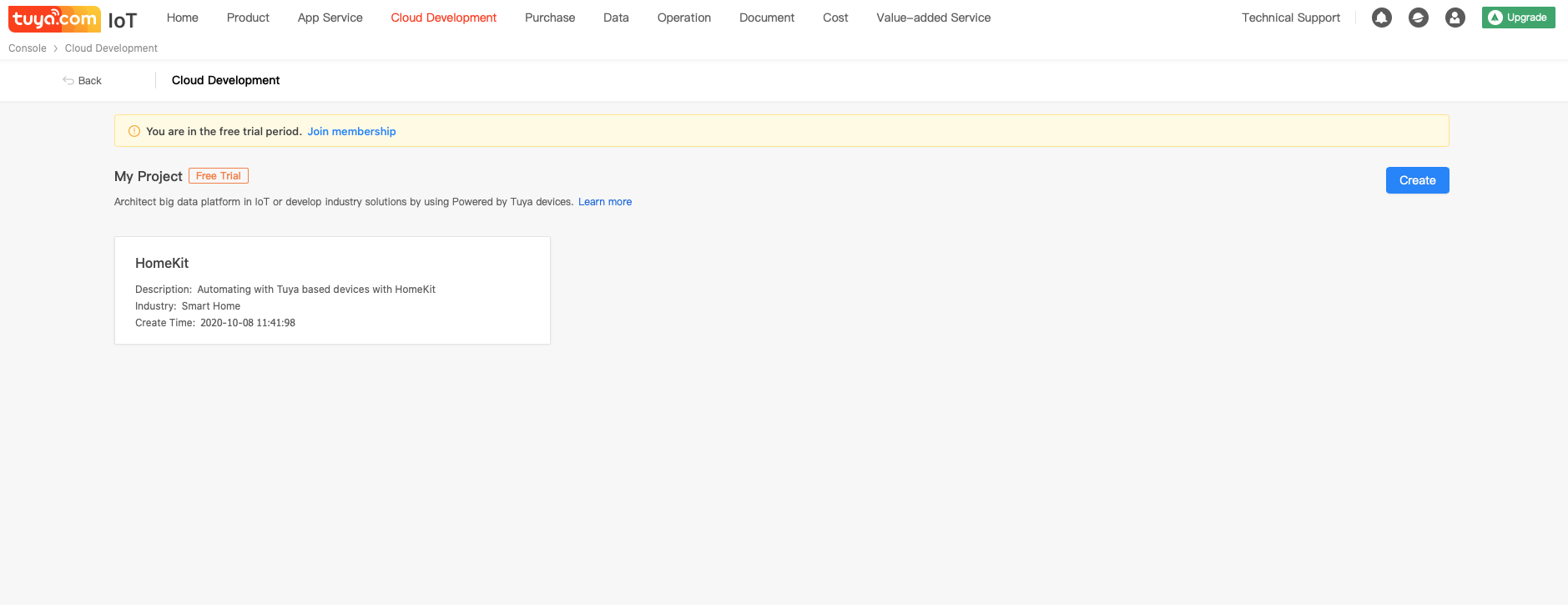
Once the account is created, I proceeded to create a project called HomeKit as part of Cloud Development. Below is a screenshot from the site.
After project creation
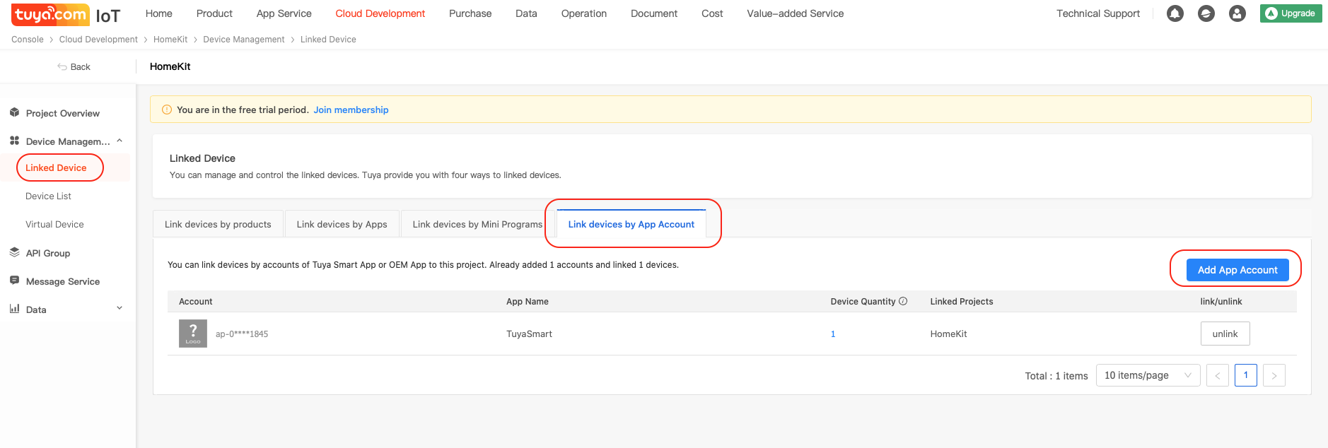
Click into the project and under Device Management, we need to link devices using the Link devices by App Account tab. When you click on the Add App Account, a QR-Code will be presented which needs to be scanned from the TuyaSmart App.
After linking the App account
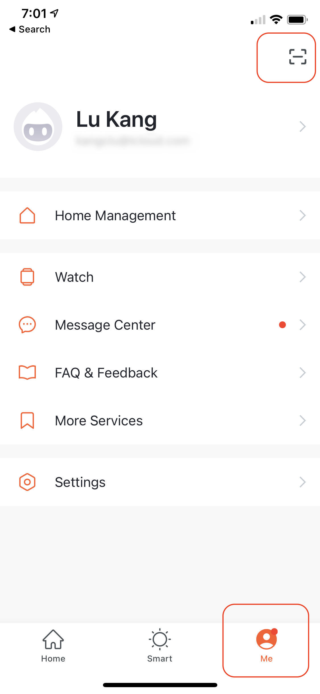
To scan the QR-Code, open the TuyaSmart App and select the Me tab at the bottom, and tap on the scan icon in the upper right hand corner.
Use TuyaSmart App to Scan QR-Code
Once the TuyaSmart App scans the QR-Code, you will see the Account along with a device count that you previously linked to your App.
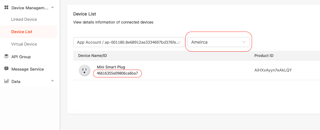
You should be able to list all the devices that you previously registered / paired with the TuyaSmart App. I had to select America before I see the devices. See below.
Devices previously added to the TuyaSmart App will be displayed
You will need the virtual id which is the identifier below the device name. Go back to Project Overview and take note of the client id and secret:
The Client ID is the same as the API key for tuya-cli
Once you have these three pieces of information, you can then find the keys for your devices that you will need to configure the homebridge-tuya plugin. To do this, execute the following (note that the API key and secret below are fake):
% DEBUG=* tuya-cli wizard
? The API key from tuya.com: akkopy4vox723px9kcb23
? The API secret from tuya.com 3hfjodfu672kfm08711kpsnbvzzuyerk
? Provide a 'virtual ID' of a device currently registered in the app: 46616355e09806ca6ba7
The above command should yield something like (again the key is fake):
Now that we have the id and key for the Gosund outlet, we can then configure Homebridge using the homebridge-tuya plugin. We use the Homebridge web interface to do this.
Homebridge Web UI
The configuration for the plugin looks something like:
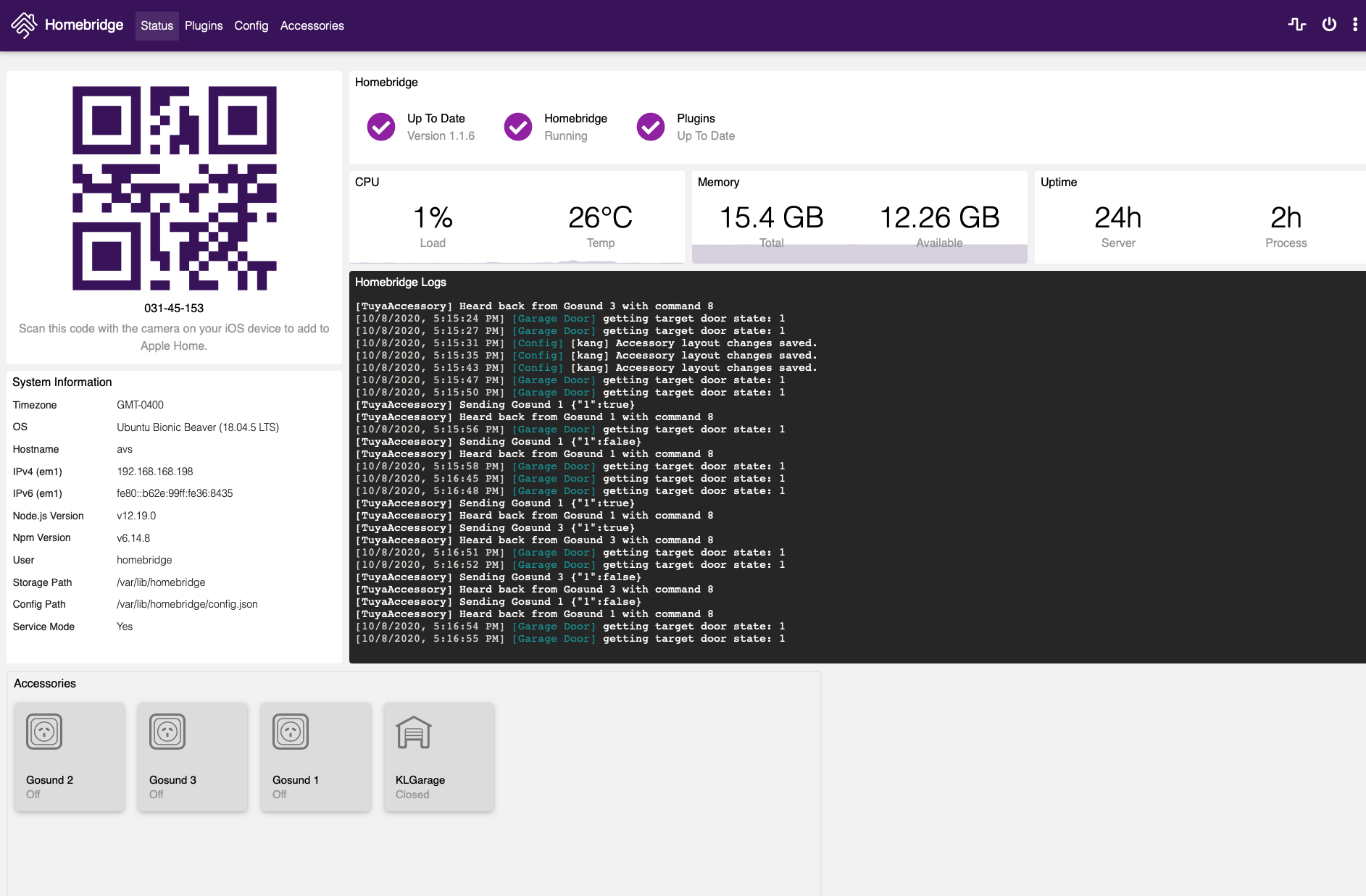
Once I restarted Homebridge on my NAS server, my Home App on my iPhone showed the smart plugs all configured. Below is what it looks like once I configured three of the Gosund smart plugs.
Home App
The integration is pretty good. The plugs are pretty cheap that I decided to buy four more.
Update: I had to add the "encoderOptions": "-preset ultrafast" property in the videoConfig object, as well as ensure the "audio" property is set to false of the homebridge-camera-ffmpeg plug-in configuration to fix the HomeKit camera streaming. With the latest version 3.0.3, the picture freezes and only get audio if this encoder option was not provided. Below is a complete sample for one of the Unifi cameras:
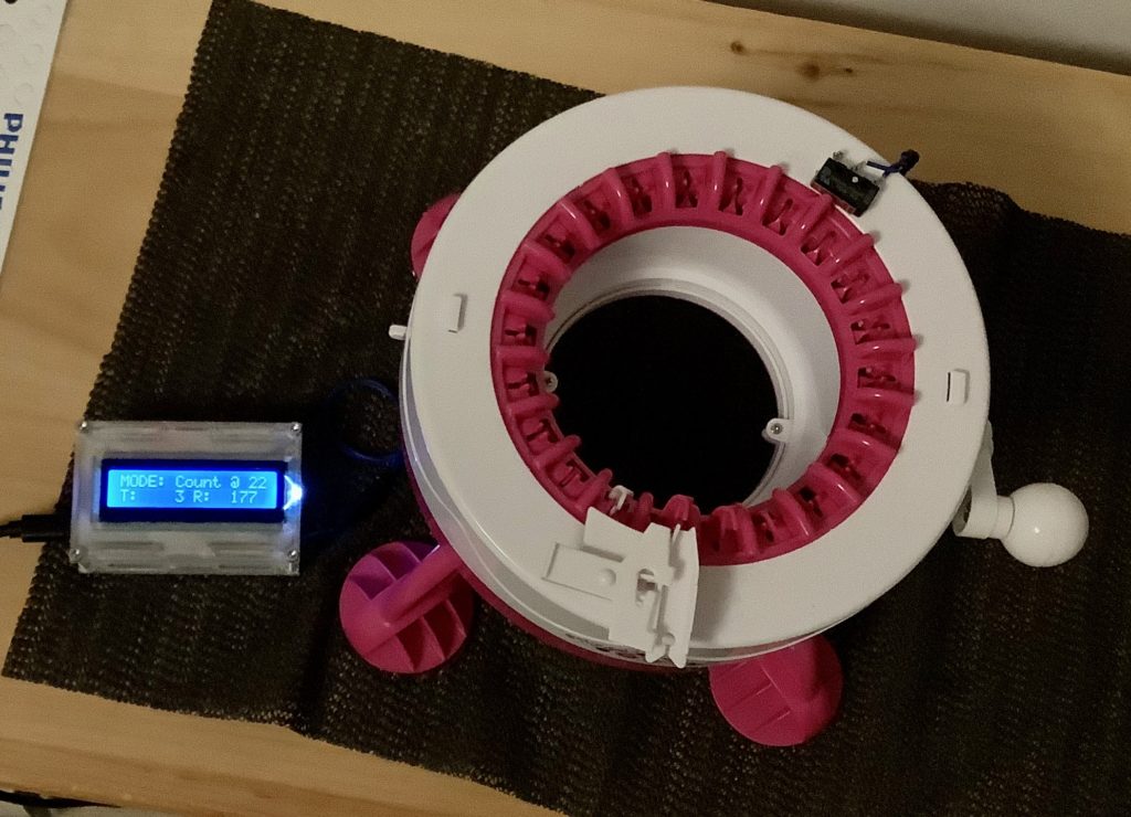
This all started when my wife started to use a circular knitting machine that she purchased recently. These machines can be used to quickly knit hats, scarfs, slippers, etc. I have seen her creating yarn goodness within a matter of minutes. The machine certainly decreases the time to produce goods when compared to traditional hand knitting by several folds. As a toy, literally, it has proven its worth several times over.
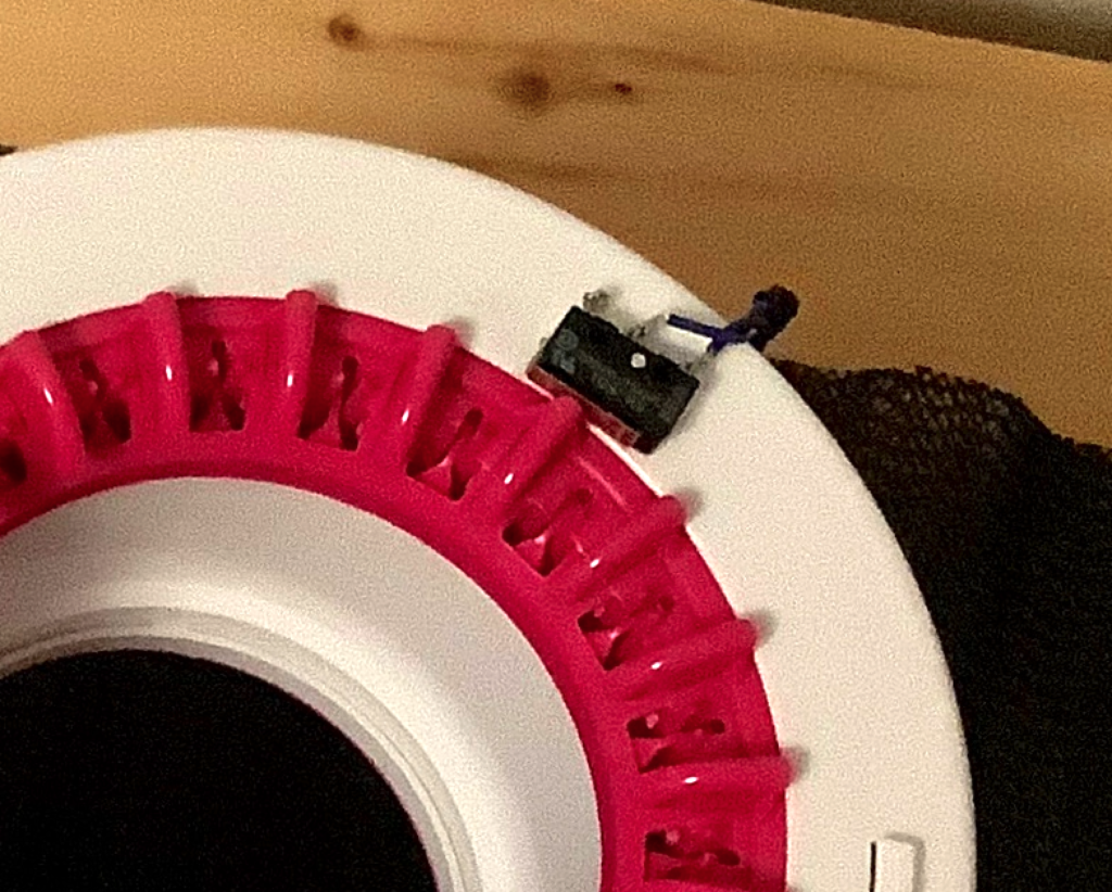
Microswitch placement
While using the machine, she has found that keeping count on the number of times the machine has revolved can be somewhat challenging. Of course this situation created a need for an electronic counter.
The idea is to use a microswitch to detect the notches on the machine, and use an ATMEGA328P microcontroller (MCU), running at 16MHz, to keep track of the count. The MCU is the same used by the famous Arduino hobby board.
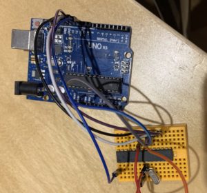
Installing the Boot Loader to an ATMEGA328P
I setup a Raspberry Pi workstation and installed the Arduino IDE on Raspbian. Using a simple circuit described here. I was able to install the boot loader and program a generic ATMEGA328P chip using an Arduino Uno board.
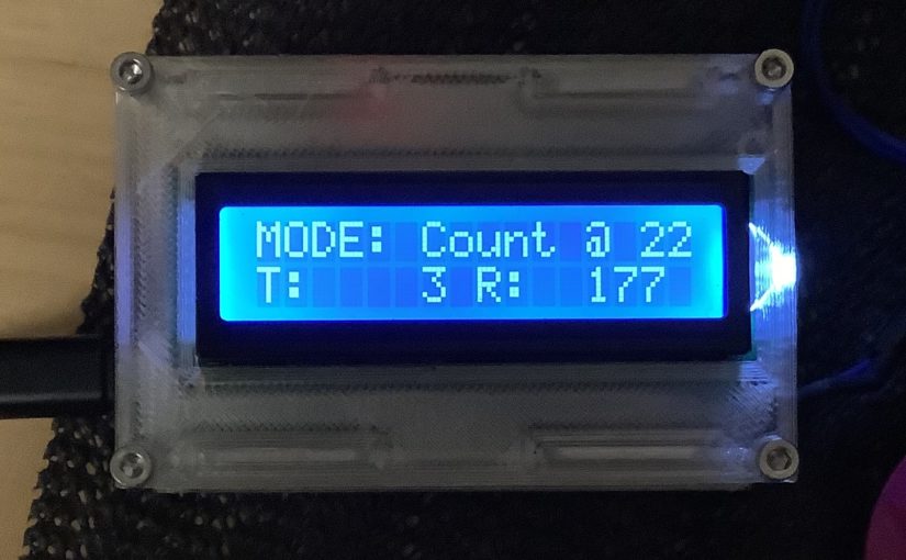
The next step is to create a simple Arduino sketch that keeps count on the number of times the microswitch has been pressed. I also enhanced the sketch to track each press as a “tick” and have the ability to remember how many ticks make a single revolution of the knitting machine. In this fashion, the counter can be used on different sizes of circular knitting machines. The goal is to count both the number of ticks and the number of revolutions knitted so far.
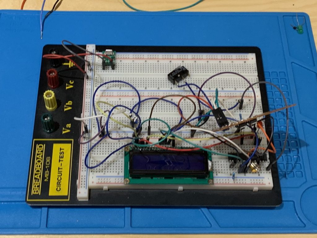
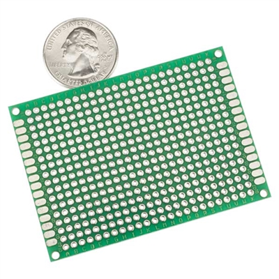
Prototype the circuit
Perfboard example
The circuit is then prototyped on a breadboard with an LCD display (LCD 1602). This was the easy part. The hardest part is to solder everything on a perfboard and then design a suitable 3D printed case.
It took many tries on the 3D printer to get certain tolerance right. Finally, putting everything together we get this:
Working counter integrated with the knitting machine!
I have to say that this work was super satisfying. As a bonus, the counter can work with any type of sensors or switches that act as Normally Open (NO) and closes when it detects or closed respectively.
As a learning process and an experiment, I would like to create a simple PCB with JCLPCB. However, I have yet to start on that yet.
This past weekend my media NAS server was intolerably slow. When I investigated, I found out that one of the RAID-1 partitions is experiencing read errors and is timing out. I decided to risk a reboot and to my surprise the RAID-1 partition did not recover with one fail drive, but mdstat recorded with an inactive status, something like this:
md2 : inactive sdc1[0](S)
After some Google search, I found that I had to do the following to resurrect the md2 device.
This reactivated the md2 partition. I replaced the failed drive and re-added the new drive to the md2 device. The RAID-1 partition is now rebuilding.
The inactive state is a new experience for me, so this was a bit of a surprise.
During this exercise I also found out that the SATA connectors on my SATA add-on card were loose causing intermittent connections. I will have to find a way to address this in the future.
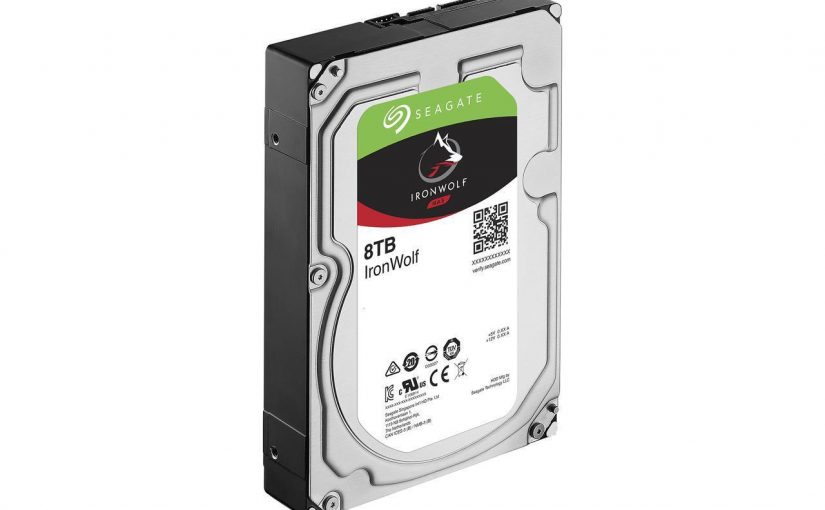
Our NAS has run out of space again. I saw a deal that the Seagate IronWolf 8TB NAS Hard Drive was on sale at newegg for $309 CAD. I jumped at the chance and purchased two.
I am now following the same step as I outlined in this post. Replacing two old 4TB drives with these two new 8TB drives.
So far so good. Hopefully when all is said and done, my NAS will have a total of 18TB in a RAID 1 configuration of 6 hard drives in total. Two 4TB, two 6TB, and the two new 8TB.
I noticed that I could fit two more drives in my chassis and may decide to re-add the two old 4 TB back in, but first I’ll have to check if my power supply can handle the demand.
I really like this mdadm and LVM setup.
Update: After 2 mdadm syncs, each of which was around 8 hours, and a pvresize that also took another 5 hours. I had to convert the filesystem from 32 bits to 64 bits using these very helpful instructions. Only after I converted to 64 bits can I then expand the existing filesystem to more than 16TB. It was a learning and yet rewarding experience. Next step is to reuse the 2 old 4TB drives in the same chassis and add them to the logical volume.