We stayed at our cousin’s place in AirDrie as he and his wife are both retired. We arrived at around 8pm on September the 18th. cousin Eddie was kind enough to slap something simple for us to eat. His rendition of the soya sauce based ribs was perfect with the steam rice that I had. At this point on the road trip, I have not had any rice for many, many days!
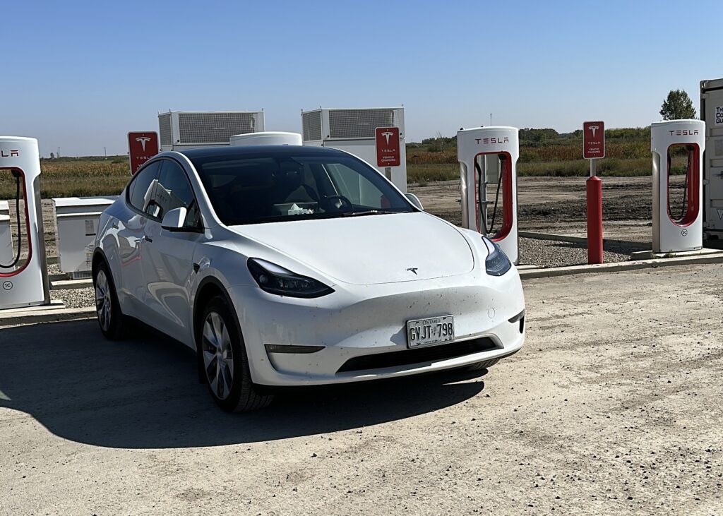
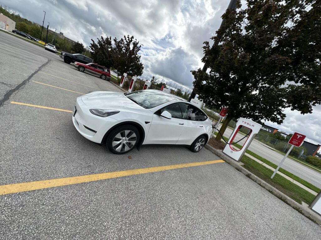
The next day we went to the CrossIron Mills Mall in Airdrie. This gives an opportunity for the girls to do some shopping while I can charge at the Tesla Supercharger that is located around the parking lots of the mall. When I got to the mall, I was surprised that it was full, and I had to queue up for a charge. After waiting for about 30 minutes, I got a stall that only gave me about 29kW. This was the slowest super charger experience yet on our road trip. The Flo fast DC charger that were next to the super chargers was faster, giving us 50kW. To make the experience worst, upon a thorough research, this was the only super charger station near Calgary! Anyone planning to drive to Calgary with a Tesla should be advised to get their vehicle charged up prior to entering the city. I gave up with the super chargers, and decided to just charge our Tesla at our cousin’s house at a measly 1kW. This means one day of plug in will only give us about 30% of charge. We didn’t do a lot of driving around town, so this worked as long as we leave the car plugged in all the time.
On the 19th, we went to cousin Rob’s place for dinner. He and his wife cooked a superb meal for us. The meat was tender and delicious, and the dinner rolls were like candy. After one, you immediately want another. It was good to catch up with them.
On the 20th, Eddie’s wife made some wonderful blueberry pancakes for us with accompanying bacon and sausages. This meal was a carb bonanza! The pancakes tasted better than my wife’s cooking. I made sure that she got the recipe. On the same evening, we went to the Modern Steak restaurant. Even though it was a steak house, and I had the Black Angus Filet, the most memorable for me were the oysters on the sea food platter. The crème brûlée also imprinted a lasting impression in my mind.
On the 21st, we woke up with some delicious pastries from La Table Haute Pastry in Airdrie. These were compliments from our cousin’s daughter and her husband. What left a real impression was the delightful almond croissant. There are no words to describe its taste. For me it was heavenly and perhaps even life changing!
Later on, we drove downtown and visited Shiki Menya Ramen for a late brunch. I had the squid ink soup, and its special savoury flavour made me want to just breathe in the ramen. Their portion was large enough that we were all stuffed. Their gyoza were also very tasty. However, in the end I had an after taste of garlic and a dying thirst for the rest of the day.
We had walk off our fullness at the Market Mall and a short visit to a local Costco for some light shopping. The garlicky flavour was alleviated by another helping of pastry from La Table when we got home. That same night we had another get together with Rob and his wife at the The Nash. It was another great opportunity to be with good company and enjoy some excellent food, especially my lamb shoulder that was cooked to perfection.
On our final full day in Calgary, the 22nd, we took our drone out to do some flying around Eddie’s gorgeous neighbourhood that was surrounded by canals lined with parallel walking paths. We use those same paths, to frequent a local Crumbl Cookies. These cookies were packed with sugar, excellent for an apocalyptic sugar rush. On our last evening in Calgary we had a super delicious meal at Ferraro Truly Italian. I had a spaghetti dish, but the pizza appetizer was out of this world. They made all their pasta and dough fresh when ordered.
This morning we bid our farewell to Calgary and our cousins on the morning of the 23rd as we head out Banff to checkout some of god’s fine landscaping. We really, really appreciated and grateful for both of our cousins to be able to share their time and residence with us. The time that we had was memorable and both Carol and I were glad that we made the trip out here to Calgary.
It is too bad that we have to make our U-Turn here, and not Vancouver or Victoria on Vancouver Island, as we must make our way back to Toronto for a wedding in October. Sorry cousin Melissa for not be able to make a visit this time around. I am pretty sure there will be a next time though.
Here is a video curated and edited by Carol on the four days that we spent in Calgary.