
Tag: technology
Ubuntu 24.04 Upgrade
Inadequate Power Causing ZFS Scrub Errors
Replacing VDEV in a ZFS Pool
Several months ago I had an old 3TB hard drive (HDD) crashed on me. Luckily it was a hard drive that is primarily used for backup purposes, so the data lost can quickly be duplicated from source by performing another backup. Since it was not critical that I replace the damaged drive immediately, it was kind of left to fester until today.
Recently I acquired four additional WD Red 6TB HDD, and I wanted to install these new drives into my NAS chassis. Since I am opening the chassis, I will irradicate the damaged drive, and also take this opportunity to swap some old drives out of the ZFS pool that I created earlier and add these new drives into the pool.
I first use the following command to add two additional mirror vdev’s each composed of the two new WD Red drives.
sudo zpool add vault mirror {id_of_drive_1} {id_of_drive_2}The drive id’s is located in the following path: /dev/disk/by-id and is typically prefixed with ata or wwn.
This created two vdev’s into the pool, and I can remove an existing vdev. Doing so will automatically start redistributing the data on the removing vdev to the other vdev’s in the pool. All of this is performed while the pool is still online and running to service the NAS. To remove the old vdev, I execute the following command:
sudo zpool remove vault {vdev_name}In my case, the old vdev’s name is mirror-5.
Once the remove command is given, the copying of data from the old vdev to the other vdev’s begins. You can check the status with:
sudo zpool status -v vaultThe above will show the copying status and the approximate time it will take to complete the job.
Once the removal is completed, the old HDD of mirror-5 is still labeled for ZFS use. I had to use the labelclear command to clean the drive so that I could repurpose the drives for backup duty. Below is an example of the command.
sudo zpool labelclear sdb1The resulting pool now looks like this:
sudo zpool list -v vault

(Output truncated)
                                                                                                                     NAME                                                    SIZE  ALLOC   FREE
vault                                                  52.7T  38.5T  14.3T
  mirror-0                                             9.09T  9.00T  92.4G
    ata-ST10000VN0008-2JJ101_ZHZ1KMA0-part1                -      -      -
    ata-WDC_WD101EFAX-68LDBN0_VCG6VRWN-part1               -      -      -
  mirror-1                                             7.27T  7.19T  73.7G
    wwn-0x5000c500b41844d9-part1                           -      -      -
    ata-ST8000VN0022-2EL112_ZA1E8S0V-part1                 -      -      -
  mirror-2                                             9.09T  9.00T  93.1G
    wwn-0x5000c500c3d33191-part1                           -      -      -
    ata-ST10000VN0004-1ZD101_ZA2964KD-part1                -      -      -
  mirror-3                                             10.9T  10.8T   112G
    wwn-0x5000c500dc587450-part1                           -      -      -
    wwn-0x5000c500dcc525ab-part1                           -      -      -
  mirror-4                                             5.45T  1.74T  3.72T
    wwn-0x50014ee2b9f82b35-part1                           -      -      -
    wwn-0x50014ee2b96dac7c-part1                           -      -      -
  indirect-5                                               -      -      -
  mirror-6                                             5.45T   372G  5.09T
    wwn-0x50014ee265d315cd-part1                           -      -      -
    wwn-0x50014ee2bb37517e-part1                           -      -      -
  mirror-7                                             5.45T   373G  5.09T
    wwn-0x50014ee265d315b1-part1                           -      -      -
    wwn-0x50014ee2bb2898c2-part1                           -      -      -
cache                                                      -      -      -
  nvme-Samsung_SSD_970_EVO_Plus_500GB_S4P2NF0M419555D   466G   462G  4.05G
The above indirect-5 can be safely ignored. It is just a reference to the old mirror-5.
This time we replaced the entire vdev, another technique is to replace the actual drives within the vdev. To do this, we will have to use the zpool replace command. We may also have to perform a zpool offline first before the replace command. This can be successively done on all the old drives in the mirror with newer drives with larger capacities to increase an existing vdev’s size.
Found Two HBA Cards for My NAS
About three weeks ago, I was casually browsing eBay and found this little gem, a Host Bus Adapter that can do PCIe 2.0 x8 (~4 to 8GB/s). This is way better than the one that I purchased earlier (GLOTRENDS SA3116J PCIe SATA Adapter Card) which can operate on a single lane of PCIe 3.0 yielding only 1GB/s. I could not pass it up at a price of only $ 40 CAD, so I purchased two of these to replace the old adapter card I had.
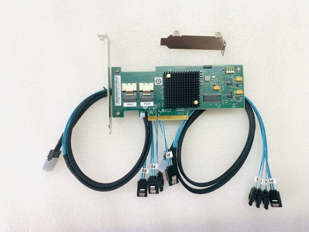
This new card LSI 6Gbps SAS HBA 9200-8i only supports 8 SATA ports per card, so I had to get two of them to support all of the hard drives that I have. These SAS HBA cards must have the IT (initiator target) mode firmware because the default firmware (IR mode) supports a version of hardware RAID, which I did not want. With the IT mode, the hard drives will be logically separated on the card and only share the physical bandwidth of the PCIe bus. This is a must for ZFS.
With these new cards, my write throughput to my NAS hard drives now averages around 500MB/s. Previously, I was only getting about half of this.
I wish I would have found these sooner. Now I have two spare PCIe SATA expansion cards, one supporting 8 ports, and the other supporting 16 ports. I will place them on another server. Perhaps in a future Proxmox cluster project.
Tesla FSD Trial
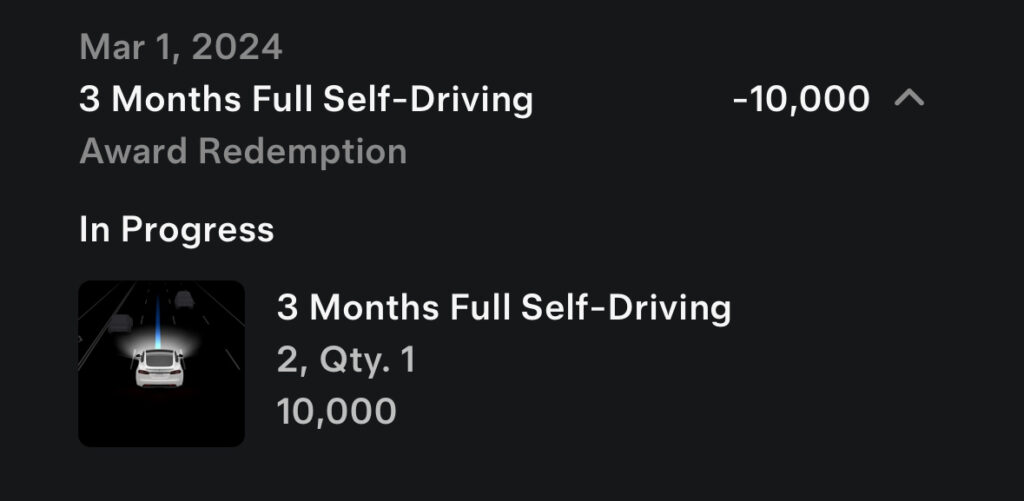
Thanks to my cousins who also purchased Tesla using my Tesla referral code, I have some referral credits that I can use to select a 3 months trial of Tesla’s Full Self Driving (FSD) capability. On March 1st, 2024, I turned this feature on.
Today, we went out for lunch at Mr. Congee in Richmond Hill, Ontario. I thought I give this FSD a try.
It was pretty easy to set up. After agreeing with all the legal stuff and enable the feature, I just set the destination, set it to drive mode, wait for the autopilot icon to show, and double tap the right stalk and away we go!
There are three settings to FSD: chill, average, aggressive/assertive. I just left it on the default, average mode.
Pulling out of the driveway, the car was a bit jerky, but once it got on the road, it made all the right decisions. I override the mode on our neighbourhood feeder road from Leslie Street just to make sure that I can override the mode, and then quickly re-engage the FSD.
On this occasion, all traveling was done on regular roads, no highways, so it was more challenging for the car. It made all the turns correctly, but I did have to override it once when it did not recognize the restricted Via Bus Lane on Yonge Street. It even pulled into the parking area at Mr. Congee, but did not fully complete the trip by parking the car. I had to park it manually.
On the way back, it hesitated too much on a left-hand turn. I had to press the accelerator to help it along. Doing this did not override the FSD mode.
I will be driving to Montreal in about 4 weeks, so I will be looking forward to testing FSD on the highway.
My initial assessment is that I probably would not have paid any more money to gain this feature. Once again, thanks to my cousins who allowed me to experience this through the use of my Tesla redemption credits.
LVM to ZFS Migration
In a previous post, I described the hardware changes that I made to facilitate additional drive slots on my NAS Media Server.
We now need to migrate from an LVM system consisting of 40TB of redundant mirrored storage using mdadm to a ZFS system consisting of a single pool and a dataset. Below is a diagram depicting the logical layout of the old and the intended new system.
Before the migration, we must backup all the data from the LVM system. I cobbled together a collection of old hard drives and then proceeded to create another LVM volume as the temporary storage of the content. This temporary volume will not have any redundancy capability, so if any one of the old hard drives fails, then out goes all the content. The original LVM system is mounted on /mnt/airvideo and the temporary LVM volume is mounted on /mnt/av2.
I used the command below to proceed with the backup.
sudo rsync --delete -aAXv /mnt/airvideo /mnt/av2 > ~/nohup.avs.rsync.out 2>&1 &I can then monitor the progress of the backup with:
tail -f ~/nohup.avs.rsync.outThe backup took a little more than 7 days to copy around 32 TB of data from our NAS server. During this entire process, all of the NAS services continued to run, so that downtime was almost non-existent.
Once the backup is completed, I wanted to move all the services to the backup before I started to dismantle the old LVM volume. The following steps were done:
- Stop all services on other machines that were using the NAS;
- Stop all services on the NAS that were using the
/mnt/airvideoLVM volume;sudo systemctl stop apache2 smbd nmbd plexmediaserver
- Unmount the
/mnt/airvideovolume, and create a soft-link of the same name to the backup volume at/mnt/av2;sudo umount /mnt/airvideosudo ln -s /mnt/av2 /mnt/airvideo
- Restart all services on the NAS and the other machines;
sudo systemctl start apache2 smbd nmbd plexmediaserver
- Once again, the downtime here was minimal;
- Remove or comment out the entry in the
/etc/fstabfile that automatically mounts the old LVM volume on boot. This is no longer necessary because ZFS is remounted by default;
Now that the services are all up and running, we can then start destroying the old LVM volume (airvideovg2/airvideo) and volume group (airvideovg2). We can obtain a list of all the physical volumes that make up the volume group.
sudo pvdisplay -C --separator ' | ' -o pv_name,vg_name

  PV | VG
  /dev/md1 | airvideovg2
  /dev/md2 | airvideovg2
  /dev/md3 | airvideovg2
  /dev/md4 | airvideovg2
  /dev/nvme0n1p1 | airvideovg2
The /dev/mdX devices are the mdadm mirror devices, each consisting of a pair of hard drives.
sudo lvremove airvideovg2/airvideo
Do you really want to remove and DISCARD active logical volume airvideovg2/airvideo? [y/n]: y
  Flushing 0 blocks for cache airvideovg2/airvideo.
Do you really want to remove and DISCARD logical volume airvideovg2/lv_cache_cpool? [y/n]: y
  Logical volume "lv_cache_cpool" successfully removed
  Logical volume "airvideo" successfully removed

sudo vgremove airvideovg2
  Volume group "airvideovg2" successfully removed
At this point, both the logical volume and the volume group are removed. We say a little prayer to ensure nothing happens with our temporary volume (/mnt/av2), that is currently in operation.
We now have to disassociate the mdadm devices from LVM.
sudo pvremove /dev/md1
Labels on physical volume "/dev/md1" successfully wiped.
sudo pvremove /dev/md2
Labels on physical volume "/dev/md2" successfully wiped.
sudo pvremove /dev/md3
Labels on physical volume "/dev/md3" successfully wiped.
sudo pvremove /dev/md4
Labels on physical volume "/dev/md4" successfully wiped.
sudo pvremove /dev/nvme0n1p1
Labels on physical volume "/dev/nvme0n1p1" successfully wiped.
You can find the physical hard drives associated with each mdadm device using the following:
sudo mdadm --detail /dev/md1
#or
sudo cat /proc/mdstat
We then have to stop all the mdadm devices and zero their superblock so that we can reuse the hard drives to set up our ZFS pool.
sudo mdadm --stop /dev/md1
mdadm: stopped /dev/md1
sudo mdadm --stop /dev/md2
mdadm: stopped /dev/md2
sudo mdadm --stop /dev/md3
mdadm: stopped /dev/md3
sudo mdadm --stop /dev/md4
mdadm: stopped /dev/md4

# Normally you also need to do a --remove after the --stop,
# but it looks like the 6.5 kernel did the remove automatically.
#
# For all partitions used in the md device

for i in sdb1 sdc1 sdp1 sda1 sdo1 sdd1 sdg1 sdn1
do
	sudo mdadm --zero-superblock /dev/${i}
done
Now with all of the old hard drives freed up, we can repurpose them to create our ZFS pool. Instead of using the /dev/sdX reference of the physical device, it is recommended to use /dev/disk/by-id with the manufacturer’s model and serial number so that the ZFS pool can be moved to another machine in the future. We also used the -f switch to let ZFS know that it is okay to erase the existing content on those devices. The command to create the pool we named vault is this:
zpool create -f vault mirror /dev/disk/by-id/ata-ST10000VN0008-2JJ101_ZHZ1KMA0-part1 /dev/disk/by-id/ata-WDC_WD101EFAX-68LDBN0_VCG6VRWN-part1 mirror /dev/disk/by-id/ata-ST8000VN0022-2EL112_ZA1E8GW4-part1 /dev/disk/by-id/ata-ST8000VN0022-2EL112_ZA1E8S0V-part1 mirror /dev/disk/by-id/ata-ST10000VN0004-1ZD101_ZA2C69FN-part1 /dev/disk/by-id/ata-ST10000VN0004-1ZD101_ZA2964KD-part1 mirror /dev/disk/by-id/ata-ST12000VN0008-2YS101_ZRT008SC-part1 /dev/disk/by-id/ata-ST12000VN0008-2YS101_ZV701XQV-part1

# The above created the pool with the old drives from the old LVM volume group
# We then added 4 more drives, 2 x 6TB, and 2 x 4TB drives to the pool

# Adding another 6TB mirror:

sudo zpool add -f vault mirror /dev/disk/by-id/ata-WDC_WD60EFRX-68L0BN1_WD-WX31D87HDU09-part1 /dev/disk/by-id/ata-WDC_WD60EZRZ-00GZ5B1_WD-WX11D374490J-part1

# Adding another 4TB mirror:

sudo zpool add -f vault mirror /dev/disk/by-id/ata-ST4000DM004-2CV104_ZFN0GTAK-part1 /dev/disk/by-id/ata-WDC_WD40EZRX-00SPEB0_WD-WCC4E0354579-part1
We also want to add the old NVMe as ZFS L2ARC cache.
ls -lh /dev/disk/by-id/nvme-Samsung_SSD_970_EVO_Plus_500GB_S4P2NF0M419555D

lrwxrwxrwx 1 root root 13 Mar  2 16:02 /dev/disk/by-id/nvme-Samsung_SSD_970_EVO_Plus_500GB_S4P2NF0M419555D -> ../../nvme0n1

sudo zpool add vault cache /dev/disk/by-id/nvme-Samsung_SSD_970_EVO_Plus_500GB_S4P2NF0M419555D
We can see the pool using this command:
sudo zpool list -v vault

NAME                                                    SIZE  ALLOC   FREE  CKPOINT  EXPANDSZ   FRAG    CAP  DEDUP    HEALTH  ALTROOT
vault                                                  45.4T  31.0T  14.4T        -         -     0%    68%  1.00x    ONLINE  -
  mirror-0                                             9.09T  8.05T  1.04T        -         -     0%  88.5%      -    ONLINE
    ata-ST10000VN0008-2JJ101_ZHZ1KMA0-part1                -      -      -        -         -      -      -      -    ONLINE
    ata-WDC_WD101EFAX-68LDBN0_VCG6VRWN-part1               -      -      -        -         -      -      -      -    ONLINE
  mirror-1                                             7.27T  6.49T   796G        -         -     0%  89.3%      -    ONLINE
    ata-ST8000VN0022-2EL112_ZA1E8GW4-part1                 -      -      -        -         -      -      -      -    ONLINE
    ata-ST8000VN0022-2EL112_ZA1E8S0V-part1                 -      -      -        -         -      -      -      -    ONLINE
  mirror-2                                             9.09T  7.54T  1.55T        -         -     0%  82.9%      -    ONLINE
    ata-ST10000VN0004-1ZD101_ZA2C69FN-part1                -      -      -        -         -      -      -      -    ONLINE
    ata-ST10000VN0004-1ZD101_ZA2964KD-part1                -      -      -        -         -      -      -      -    ONLINE
  mirror-3                                             10.9T  8.91T  2.00T        -         -     0%  81.7%      -    ONLINE
    ata-ST12000VN0008-2YS101_ZRT008SC-part1                -      -      -        -         -      -      -      -    ONLINE
    ata-ST12000VN0008-2YS101_ZV701XQV-part1                -      -      -        -         -      -      -      -    ONLINE
  mirror-4                                             5.45T  23.5G  5.43T        -         -     0%  0.42%      -    ONLINE
    ata-WDC_WD60EFRX-68L0BN1_WD-WX31D87HDU09-part1         -      -      -        -         -      -      -      -    ONLINE
    ata-WDC_WD60EZRZ-00GZ5B1_WD-WX11D374490J-part1         -      -      -        -         -      -      -      -    ONLINE
  mirror-5                                             3.62T  17.2G  3.61T        -         -     0%  0.46%      -    ONLINE
    ata-ST4000DM004-2CV104_ZFN0GTAK-part1                  -      -      -        -         -      -      -      -    ONLINE
    ata-WDC_WD40EZRX-00SPEB0_WD-WCC4E0354579-part1         -      -      -        -         -      -      -      -    ONLINE
cache                                                      -      -      -        -         -      -      -      -  -
  nvme-Samsung_SSD_970_EVO_Plus_500GB_S4P2NF0M419555D   466G  3.58G   462G        -         -     0%  0.76%      -    ONLINE
Once the pool is created, we wanted to set some pool properties so that in the future when we replace these drives with bigger drives, the pool will automatically expand.
zpool set autoexpand=on vaultWith the pool created, we can then create our dataset or filesystem and its associated mount point. We also want to ensure that the filesystem also supports posixacl.
zfs create vault/airvideo
zfs set mountpoint=/mnt/av vault/airvideo
zfs set acltype=posixacl vault
zfs set acltype=posixacl vault/airvideo
We mount the new ZFS filesystem on /mnt/av because the /mnt/airvideo is soft-linked to the temporary /mnt/av2 volume that is still in operation. We first have to re-copy all our content from the temporary volume to the new ZFS filesystem.
sudo rsync --delete -aAXv /mnt/av2/ /mnt/av > ~/nohup.avs.rsync.out 2>&1 &This took around 4 days to complete. We can all breathe easy again because all the data now have redundancy again! We can now bring the new ZFS filesystem live.
sudo systemctl stop apache2.service smbd nmbd plexmediaserver.service
sudo rm /mnt/airvideo
sudo zfs set mountpoint=/mnt/airvideo vault/airvideo
sudo systemctl start apache2.service smbd nmbd plexmediaserver.service

zfs list

NAME             USED  AVAIL     REFER  MOUNTPOINT
vault           31.0T  14.2T       96K  /vault
vault/airvideo  31.0T  14.2T     31.0T  /mnt/airvideo
The above did not take long and the migration is completed!
df -h /mnt/airvideo

Filesystem      Size  Used Avail Use% Mounted on
vault/airvideo   46T   32T   15T  69% /mnt/airvideo
Getting the capacity of our new ZFS filesystem shows that we now have 46TB to work with! This should last for at least a couple of years I hope.
I also did a quick reboot of the system to ensure it can come back up with the ZFS filesystem in tack and without issues. It has now been running for 2 days. I have not collected any performance statistics, but the services all feel faster.
Media Server Storage Hardware Reconfiguration
Our media server has reached 89% utilization and needs storage expansion. The storage makeup on the server uses Logical Volume Manager (LVM) and software RAID called mdadm. I can expand the storage by swapping out the hard drives with the least capacity with new hard drives with a larger capacity like I have previously done.
I thought I try something different this time around. I would like to switch from LVM to ZFS, an LVM alternative that is very popular with modern mass storage systems, especially with TrueNAS.
Before I can attempt the conversion, I will first need to backup all of the content from the media server. The second issue is that I needed more physical expansion space on the server to house more hard drives. The existing housings are all filled except for a single slot, which is going to be insufficient.
A related issue is that I no longer have any free SATA slots available for the new hard drives, so I purchased GLOTRENDS SA3116J PCIe SATA Adapter Card with 16 SATA Ports. Once this is installed, I have more than enough SATA ports for additional storage.
One downside of the SATA card is that it is limited to PCIe 3.0 x1 speed. This means data transfer is limited to a theoretical maximum of 1GB/s. Given that the physical hard drives top out at 200MB/s, I don’t think we need to be too concerned about this bottleneck. We will see in terms of practical usage in the future.
I am so lucky to have extra SATA power cables and extension cables laying around and my 850W existing power supply has ample power for the additional hard drives.
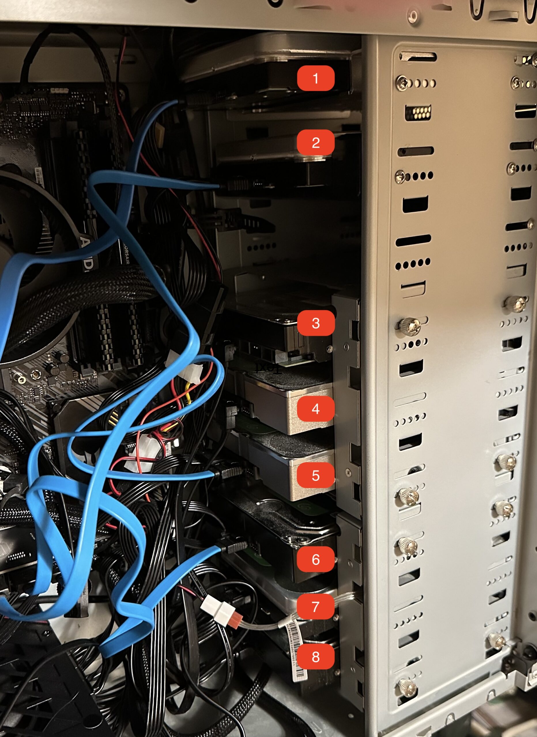
How do we store the additional hard drives with a full cabinet? I went to Amazon again and purchased a hard drive cage, Jaquiain 3.5 Inch HDD Hard Drive Cage 8X3.5 Inch HDD Cage. I did not have to buy any new hard drives yet, because I had plenty of old hard drives laying around. After I put together the cage with 8 really old and used hard drives, it looks something like this:
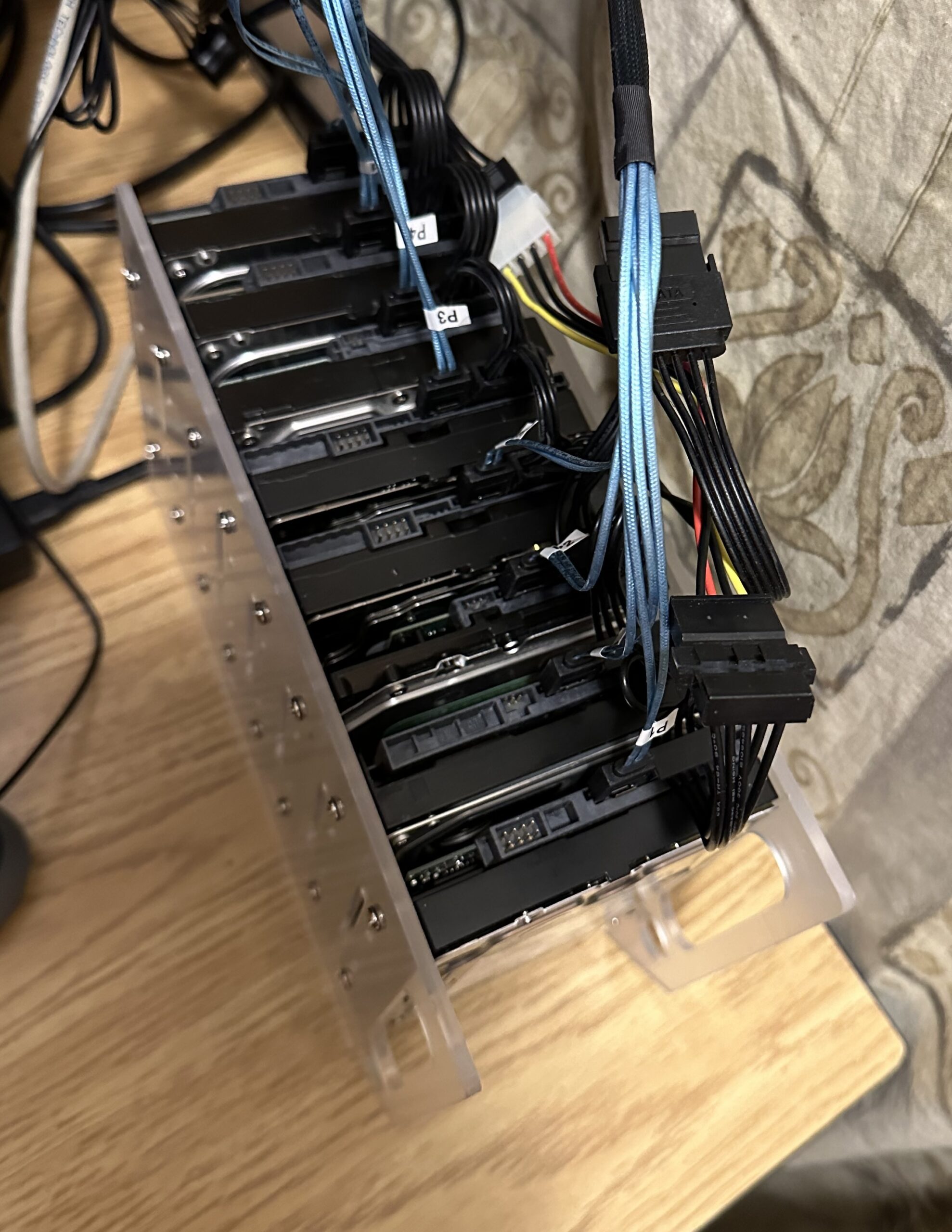
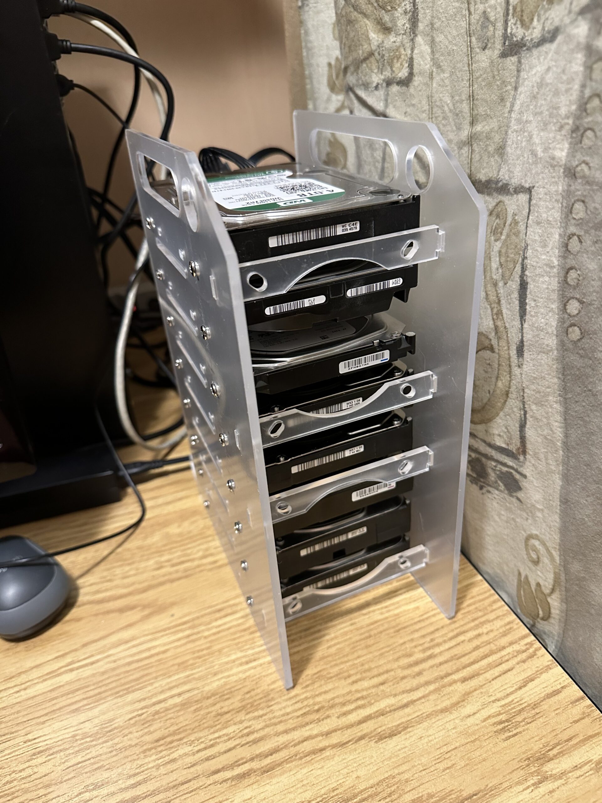
With this new additional storage, I am now able to backup the media content from my media server. However, before I do that there is one last thing that I need to do, and that is to experiment with an optimal ZFS pool configuration that will work with my content and usage. I will perform this experimentation with the additional storage before reconfiguring the old storage with ZFS. Please stay tuned for my findings.
After booting the system with 16 hard drives, I measured the power usage and it was hovering around 180W. This is not too bad, less than 2 traditional incandescent light bulbs.
Addendum:
During my setup, I had to spend hours deciphering an issue. My system did not recognize my old hard drives. After many trials, I finally narrowed down that the GLOTRENDS card is not compatible with an old 2TB Western Digital Enterprise Drive. This is the first time that I came across SATA incompatibilities.
There is another possibility that these drives were damaged by the usage of an incorrect modular power cable. I found that these drives also do not work with my USB3.0 HDD external dock as well. This gives additional credence that the physical drive has been damaged.
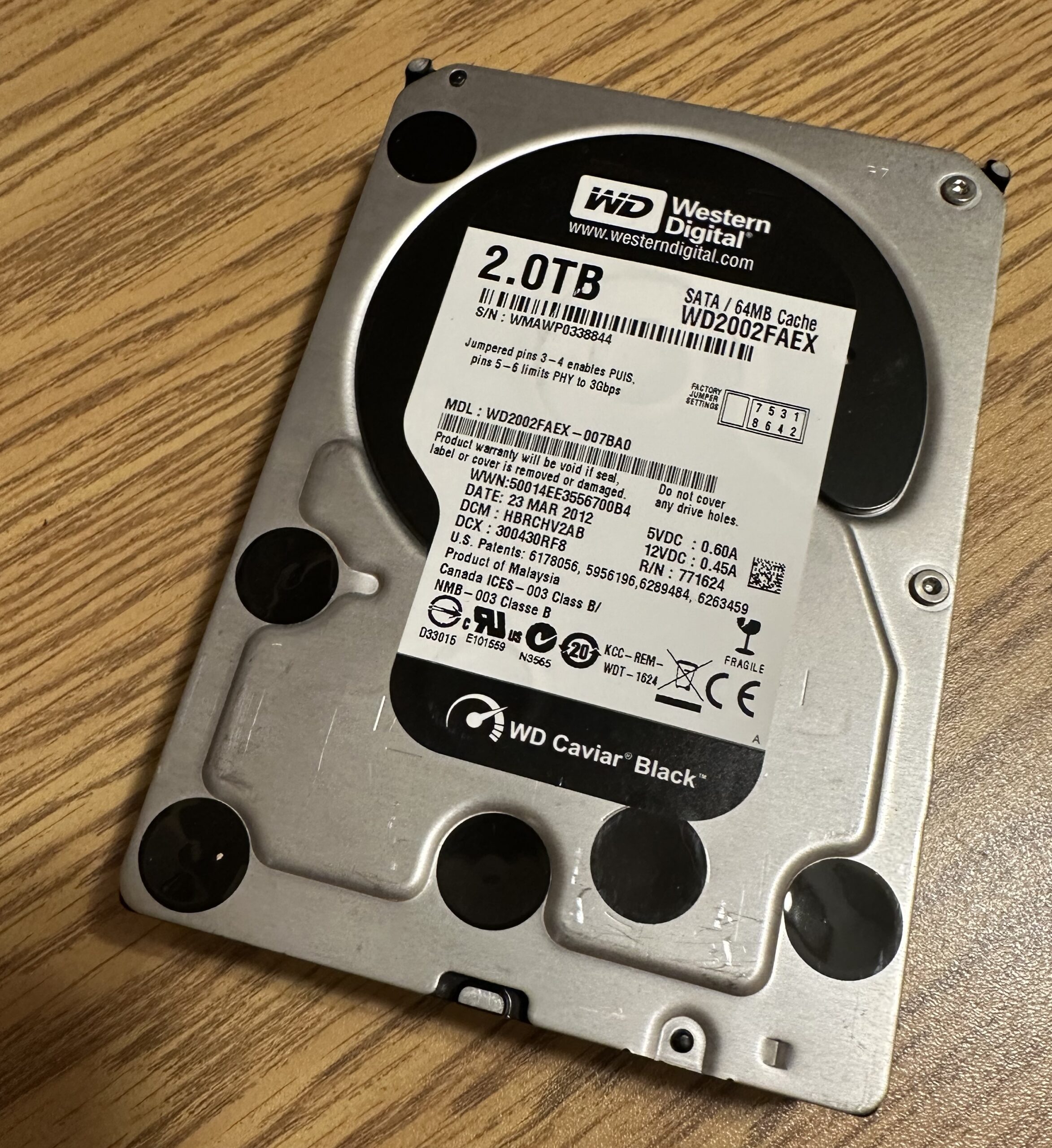
All my other drives worked fine with the card.
Another discovery is that not all modular power cables will work with my ASUS ROG STRIX 850W power supply. Initially, I thought I would use an 8-pin PCIe to 6-pin adapter along with a 6-pin to SATA power cable designed for Corsair power supplies.
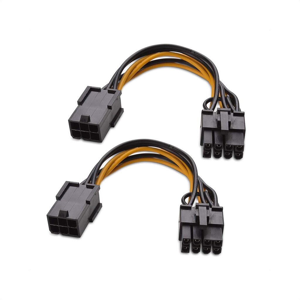
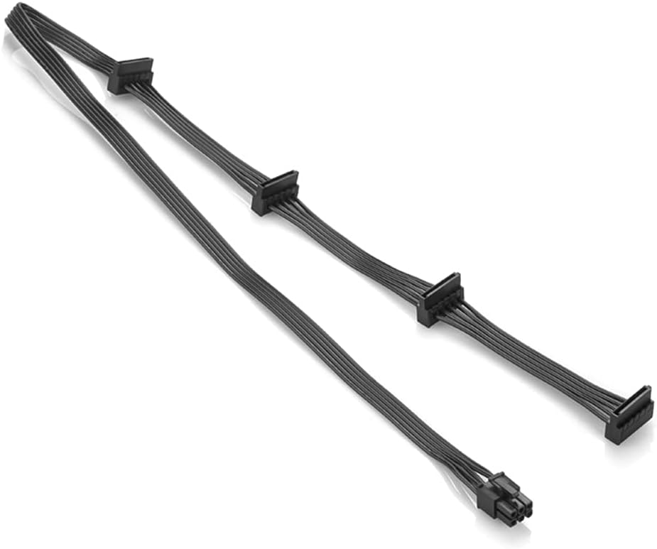
Using the above cables will cause the power supply not to start. I had to hunt for the original cables that came with the STRIX power supply.
Learned a lot from rejigging this media server. My reward is to see my server boot up with 16 hard drives and 2 NVMe SSD drives recognized. I have never built a system with so many drives and storage before.
Wake-on-LAN for Linux
My sons upgraded their gaming computers last Christmas, and I ended up using their old parts to build a couple of Linux servers running Ubuntu servers. The idea is to use these extra servers as video encoders since they will have dedicated GPUs. However, the GPUs are also pretty power-hungry. Since they don’t need to be up 24 hours a day, I thought keeping these servers asleep until they are required would be good. At the same time, it would be pretty inconvenient to go to the servers to physically power them up when I needed them. The thought of configuring their Wake-on-LAN came to mind.
I found this helpful article online. I first found out that the Network Interface on the old motherboards supports Wake-on-LAN (WOL). Below is a series of commands that I executed to find out whether WOL is supported or not, and if so, then enable the support.
% sudo nmcli connection show
NAME                UUID                                  TYPE      DEVICE
Wired connection 1  d46c707a-307b-3cb2-8976-f127168f80e6  ethernet  enp2s0

% sudo ethtool enp2s0 | grep -i wake
	Supports Wake-on: pumbg
	Wake-on: d
The line that reads,
Supports Wake-on: pumbgindicates the WOL capabilities, and the line that reads,
Wake-on: d
indicates its current status. Each letter has a meaning:
- d (disabled), or
- triggered by
- p (PHY activity),
- u (unicast activity),
- m (multicast activity),
- b (broadcast activity),
- a (ARP activity),
- g (magic packet activity)
We will use the magic packet method. Below are the commands used to enable WOL based on the magic packet trigger.
% sudo nmcli connection modify d46c707a-307b-3cb2-8976-f127168f80e6 802-3-ethernet.wake-on-lan magic

% sudo nmcli connection up d46c707a-307b-3cb2-8976-f127168f80e6
Connection successfully activated (D-Bus active path: /org/freedesktop/NetworkManager/ActiveConnection/2)

% sudo ethtool enp2s0 | grep -i wake
	Supports Wake-on: pumbg
	Wake-on: g
The above changes will persist even after the machine reboots. We put the machine to sleep by using the following command:
% sudo systemctl suspendWe need the IP address and the MAC address of the machine to wake the computer up using the wakeonlan utility.
% ifconfig
enp2s0: flags=4163<UP,BROADCAST,RUNNING,MULTICAST>  mtu 1500
        inet 192.168.168.185  netmask 255.255.255.0  broadcast 192.168.168.255
        inet6 fd1a:ee9:b47:e840:6cd0:bf9b:2b7e:afb6  prefixlen 64  scopeid 0x0<global>
        inet6 fe80::41bc:2081:3903:5288  prefixlen 64  scopeid 0x20<link>
        inet6 fd1a:ee9:b47:e840:21b9:4a98:dafd:27ee  prefixlen 64  scopeid 0x0<global>
        ether 1c:1b:0d:70:80:84  txqueuelen 1000  (Ethernet)
        RX packets 33852015  bytes 25769211052 (25.7 GB)
        RX errors 0  dropped 128766  overruns 0  frame 0
        TX packets 3724164  bytes 4730498904 (4.7 GB)
        TX errors 0  dropped 0 overruns 0  carrier 0  collisions 0
We use the above ifconfig to find the addresses highlighted in bold. Once we have the required information, we can then wake the computer up remotely by executing the wakeonlan command from another computer.
% wakeonlan -i 192.168.168.255 -p 4343 1c:1b:0d:70:80:84
Sending magic packet to 192.168.168.185:4343 with 1c:1b:0d:70:80:84
Note that the above IP address used is the broadcast address and not the machine’s direct IP address. Now I can place these servers to sleep and only turn them on remotely when I need them.
EXT4-fs Errors on NVME SSD
In my previous post, I replaced my NVME boot disk on our media server thinking that the disk was defective because the file system (EXT4-fs) was reporting numerous htree_dirblock_to_tree:1080 errors.
The errors continue to persist with the new disk, so I can eliminate the possibility of hardware as the cause of the issue.
I noticed that the htree_dirblock_to_tree:1080 errors were caused by the tar command and the time in which these errors occur coincided when the media server is being backed up. Apparently, the backup process is causing these errors with the tar command.
This backup process has remained unchanged for quite some time and has worked really well for us. I guess for some reason there is a bug in the kernel or in the tar command that is not quite compatible with NVME devices.
I had to resort to finding an alternative backup methodology. I ended up using the rsync method instead.
sudo rsync --delete \
  --exclude 'dev' \
  --exclude 'proc' \
  --exclude 'sys' \
  --exclude 'tmp' \
  --exclude 'run' \
  --exclude 'mnt' \
  --exclude 'media' \
  --exclude 'cdrom' \
  --exclude 'lost+found' \
  --exclude 'home/kang/log' \
  -aAXv / /mnt/backup
It looks like this method is faster and can perform incremental backup. However, instead of backing up to an archive file, which I later need to extract and prepare during the restoration process, I have to back it up to a dedicated backup device. Since the old NVME disk is perfectly fine, I reused it as my backup device. I have partitioned this backup device in the same layout as the current boot disk.
Device          Start        End    Sectors   Size Type
/dev/sdi1        2048    2203647    2201600     1G Microsoft basic data
/dev/sdi2     2203648 1921875967 1919672320 915.4G Linux filesystem
/dev/sdi3  1921875968 1953523711   31647744  15.1G Linux swap
The only exception is that the first partition is not marked as boot and esp, so during the restoration process I will have to mark that partition accordingly with the parted command by using the following commands:
set 1 boot on
set 1 esp on
The idea is that at 3am every night/morning, I will backup the root filesystem to the second partition of the backup drive. If anything happens with the current boot disk, the backup drive can act as an immediately available replacement, after a grub-install preparation as mentioned in the previous article.
Let us see how this new backup process works and hopefully, we can bid a final farewell to the htree_dirblock_to_tree:1080 errors!
Update: 2023-12-22
It looks like even with the rsync command, the htree_dirblock_to_tree:1080 errors still came back during the backup process. I decided to upgrade the kernel from vmlinuz-5.15.0-91-generic to vmlinuz-6.2.0-39-generic. Last night (2023-12-23 early morning) was the first backup after the kernel upgrade, and no errors were recorded. I hope this behavior persists and it is not a one-off.