Today is January 13, 2023. We had an icy snow storm last night that lasted until this morning, and I was curious what the roof condition was like. Just how much of the panels were covered in snow?
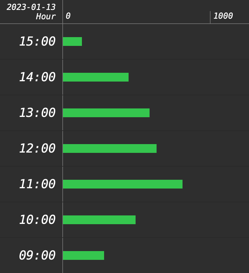
Solar energy for today
Our peak energy production was at around 11am when we generated a little over 800Wh, which is inlined with what we kind of get on a cloudy, misty, winter day. In contrast, the best we got so far was on January 7th at 1pm. We generated 5,494Wh. That was a sunny day with no snow coverage on the panels.
A quick drone survey of our roof this afternoon at around 3pm.
I was kind of impressed that we got that much with so much of the panels covered. Watch the above video to see just how much of the panels are covered today. Our total production for today is only about 3,400Wh.
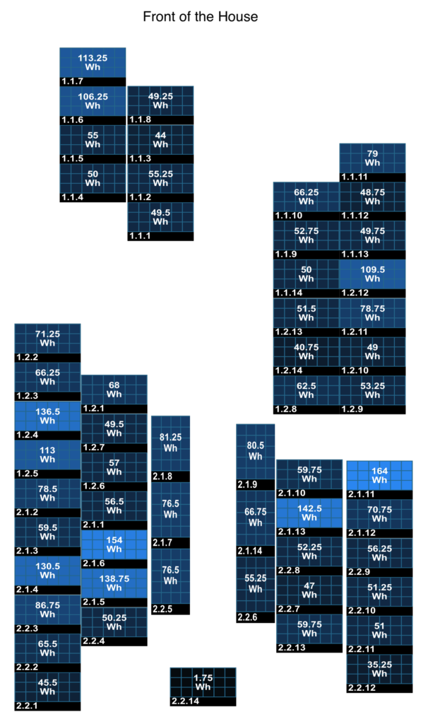
Below are the stats per panel.
Per panel generation statistics for today.
As you can see above, every panel contributed even the covered ones! There will be two sunny days over the weekend, so we will see!
Update: 2023-01-14
I did another roof survey with my drone, seeing that today it was a sunny sky day.
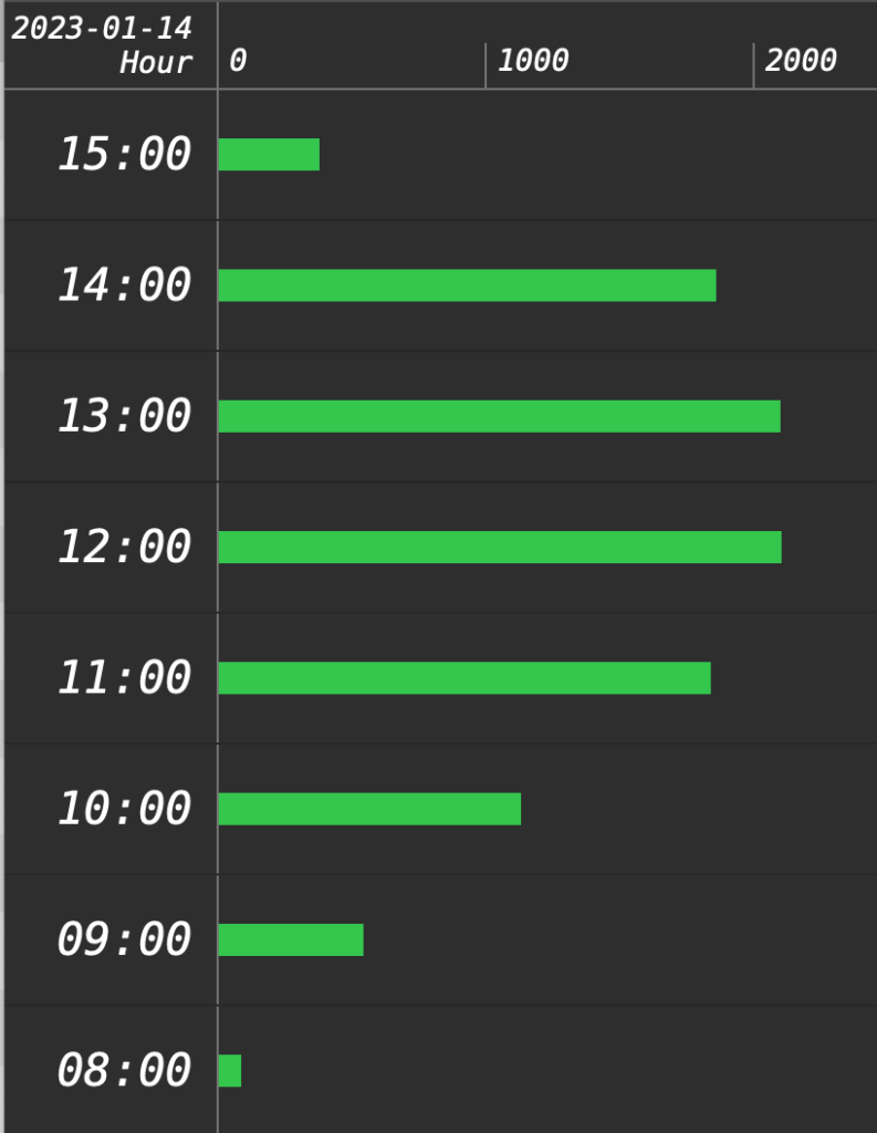
Roof survey on Jan. 14 (day after storm)Solar energy production on Jan. 14
We have generated over 10,000 Wh of energy today about 3 times more than yesterday. The survey was conducted when it was still -6 ºC outside, so way below freezing.
I have a membership with Audible and I sometimes also get other audio book sources. Recently I experimented with combining all of my audio books into a centralized place. Since I already have a Plex server running, I thought it would be a good place to do this.
I did a little research and came across a couple of very helpful articles:
I have a single folder to store all of my audio books. Inside the folder, each audio book is stored as an “m4b” file.
Ensure that audio books have a poster image and that its artist and album_artist tags are set to the author. Where appropriate, the audio book should also contain chapter metadata.
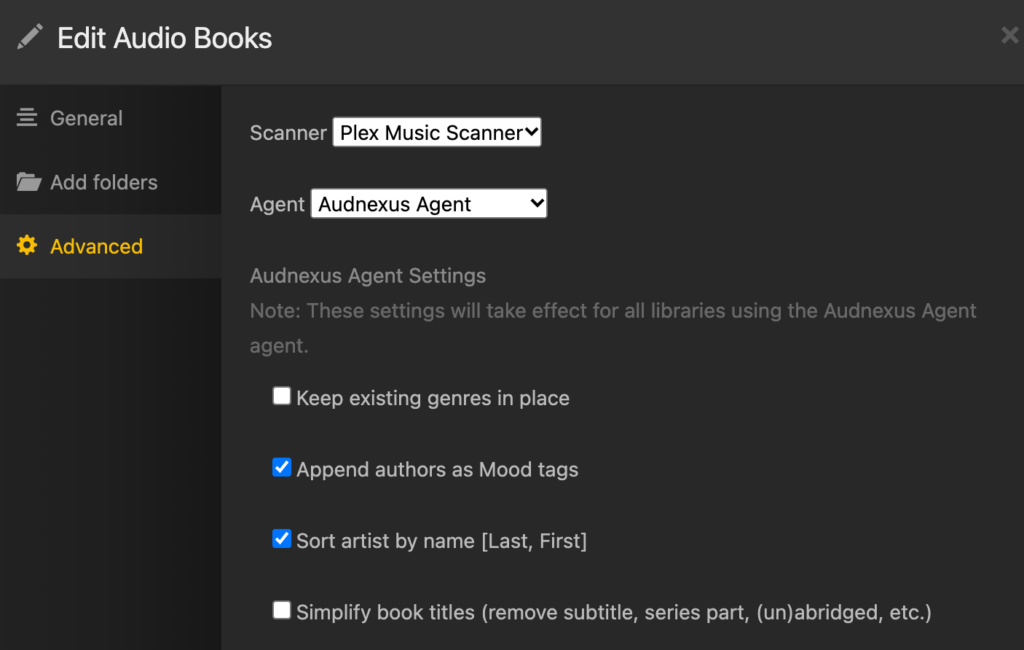
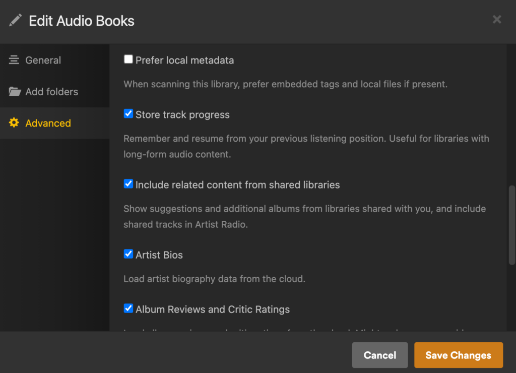
Create a music library on Plex by adding the audio book folder, and set the agent to Audnexus
Note the Agent setting
Ensure that the advanced option of “Store track progress” is checked.
Ensure that Store Track Progress is checked!
Each book in the library will be represented as an album, and the author will be mapped to album artist. Once the library is created, you can download and play the audio books from the desktop using the Plex app. However, the more common use case is to listen to the audio books while on the go.
Using Prologue to Play Audio Books
We first have to download the Prologue App. I did not get any of the In-App premium functionality, and just stayed with the free version.
Point the app to my Plex server’s URL, and all the audio books from the library should now be accessible and playable on the iPhone or iPad with chapter, bookmark, and last-left-position support.
This is a really neat solution, and I am impressed how Plex and Prologue together formed a dynamic duo in this manner.
My wife and I were watching Lighter & Princess (点燃我,温暖你). In episode 5, a smart programmer completed a heart animation as part of a programming test in a university course. Everyone of his classmates had a mediocre and simplistic implementation.
My wife challenged me to do the same. I could have done this with SVG and Javascript, but I took the opportunity to learn more Python and Qt. The latter I have not used at all and was always curious how well it worked with Python. I decided to use the PyQt package instead of the PySide package.
I hacked this together today resulting in this rendition:
Click above to see it in action
The PyQt implementation worked really well across Windows, Mac, and Ubuntu Linux. I suppose the Javascript and SVG would have done the same, but I learned something new in this case.
The source code and the installation instructions are at:
In the first part of this post, I talked about making sure all the new hardware that I recently purchased works. Yesterday, upgrading from Ubuntu 20.04 LTS to 22.04 LTS was super simple. Unfortunately, that was the end of the easy part.
I thought I could just image by old boot drive and make a carbon copy of it on my new boot drive. My old boot drive is a simple SATA 512GB SSD, and my new boot drive is an NVMe M.2 1TB SSD plugged directly to the motherboard. The copying was pretty simple, but because the drives differ in size, I had to relayout the partition table with the new drive once the copy is completed. I did this with the parted command.
Unfortunately the new boot drive did not want to boot. At this point I had to do some research. The most helpful articles were:
Both of the above articles were an excellent refresher on how GRUB works. I have used GRUB since the beginning, but one gets super rusty when these types of tasks are only performed once every three or six years!
Instead of detailing what went wrong, I will just explain what I should have done. This way if I need it again in the future, it is here for my reference.
Step 1: Perform a backup of the old boot drive from a Live USB in shell mode. This is done on my server on a nightly basis. This method is clearly described on the Ubuntu Community Help Wiki.
Following this method I will end up with a compressed tar archive for my entire root directory, skipping some runtime and other unwanted directories.
Step 2: After installing a fresh install of the new Ubuntu LTS Server operating system on the new server and boot drive, I proceeded to backup the new boot with the same technique used in Step 1. I stored the backup of the new install on another external SSD drive that I have lying around. Also it is important that new boot drive partition layout of the new install contains a swap partition.
Step 3: I then restore the most recent backup (done in Step 1) of the old boot drive to the new boot drive. I then replaced the /boot/grub directory with the new contents from the new install which was backed up in Step 2. The new GRUB is already installed when we performed a brand new installation on the drive. We just want to make sure the boot partition matches the /boot/grub contents.
Step 4: We also need to fix up the /etc/fstab file because it contains references to drive devices from the old hardware. Paid special attention the main data partition and the swap partition. It should look something like this:
# /etc/fstab: static file system information.
#
# Use 'blkid' to print the universally unique identifier for a
# device; this may be used with UUID= as a more robust way to name devices
# that works even if disks are added and removed. See fstab(5).
#
# <file system> <mount point>   <type>  <options>       <dump>  <pass>
# / was on /dev/nvme1n1p2 during curtin installation
UUID=fc939be4-5292-4252-8120-7ef59b177e5b / ext4 defaults 0 1

# /boot/efi was on /dev/nvme0n1p1 during curtin installation
UUID=5187-A8C6 /boot/efi vfat defaults 0 1

# Swap partition
UUID=512d611e-6944-4a57-9748-ea68e9ec3fad	none	swap	sw	0	0

# /dev/mapper/airvideovg2-airvideo /mnt/airvideo ext4 rw,noatime 0 0
UUID=9e78425c-c1f3-4285-9fa1-96cac9114c55 /mnt/airvideo ext4 rw,noatime 0 0
Noticed that I also added the LVM logical volume for /mnt/airvideo, which is my RAID-1 array. The UUID can be obtained by the blkid command. Below is a sample output:
Step 4B (Potentially): If the system boots in the “grub>” prompt, then we will have persuade grub to manually boot by providing the following at the prompt:
grub> set root=(hd9,gpt2)
grub> linux /boot/vmlinuz root=/dev/nvme1n1p2
grub> initrd /boot/initrd.img
grub> boot
To find the root value on the first line, you have use the ls command which is explained in this article. The root parameter on the linux line references the partition which the root directory is mounted. In my case, it was /dev/nvme1n1p2.
After I rebooted, I reinstalled GRUB with the following as super user:
grub-install /dev/nvme1n1
It may also be required to update our initramfs using:
update-initramfs -c -k all
Step 5: At this point the system should reboot and all of the old server’s content should now be on the old hardware. Unfortunately we will need to fix the network interface.
First obtain the MAC address of the network interface using:
% sudo lshw -C network | grep serial
    serial: 04:42:1a:05:d3:c4
And then we will have to edit the /etc/netplan/00-installer-config.yaml file.
% cat /etc/netplan/00-installer-config.yaml
# This is the network config written by 'subiquity'
network:
  ethernets:
    enp6s0:
      dhcp4: true
      match:
        macaddress: 04:42:1a:05:d3:c4
      set-name: enp6s0
  version: 2
Ensuring the MAC address matches from lshw and that the name is the same as the old system. The name in this example is enp6s0. We then need to execute the following commands to generate the interface.
netplan generate
netplan apply
We need to ensure the name matches because many services on the server have configurations that references the interface name, such as:
Configurations in /var/network/interfaces
Samba (SMB) (/etc/samba/smb.conf)
Pihole (/etc/pihole/setupVars.conf)
Homebridge (/var/lib/homebridge/config.json)
Step 6: Fix the router provisioning DHCP IP addresses so that the new server has the same fixed IP address as the old server. This is important because there may be firewall rules referencing this IP address directly. The hostname should have been automatically restored when we restored the partition in Step 3.
Step 7: Our final step is to test the various services and ensure they are working properly. These include:
On May 15th, 2019 (more than three years ago), I performed a performance boost to my media server by upgrading its CPU, Motherboard, and Memory. You can read that experience in this post.
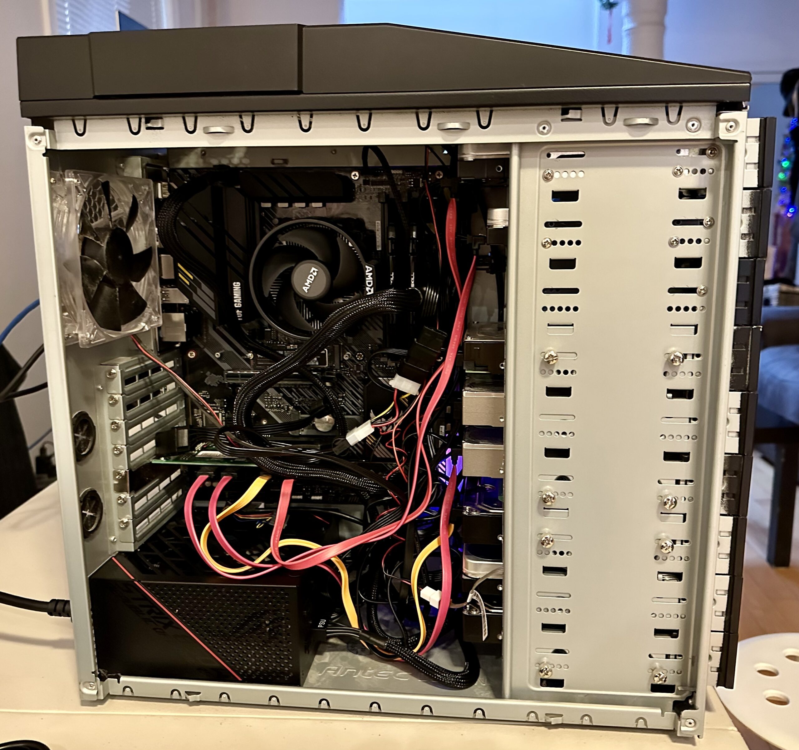
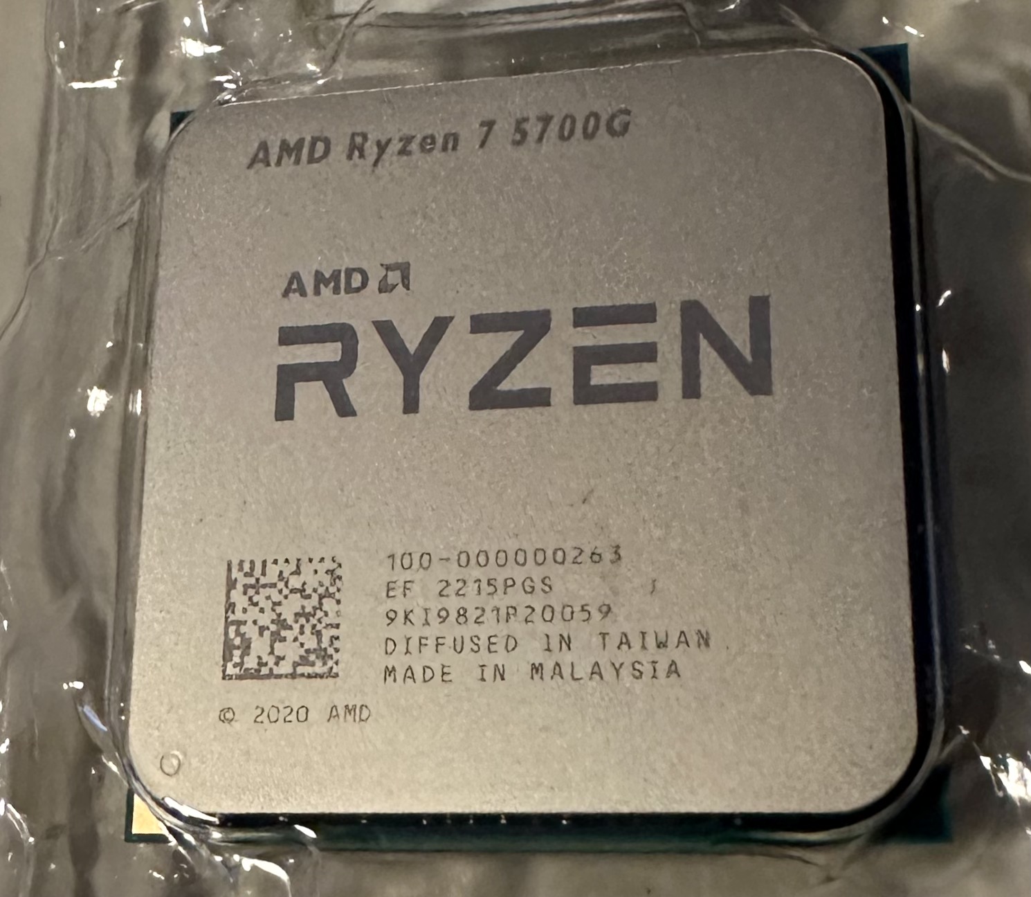
Today, I am going to be doing the same. It looks like we are on a cadence of every 3 years or so to do a spec bump. This time around we are also changing the same items, but will include the power supply as well in the swap. I also decided to swap the boot drive hardware from an old SSD drive to an NVME drive. All of this resulted in the following hardware acquisitions, all from Amazon, which I find them to have lower pricing (when factoring free shipping through Prime), than Newegg even during Black Friday and Cyber Monday offers.
The plan is to spend the time today to roughly test out all the new hardware.
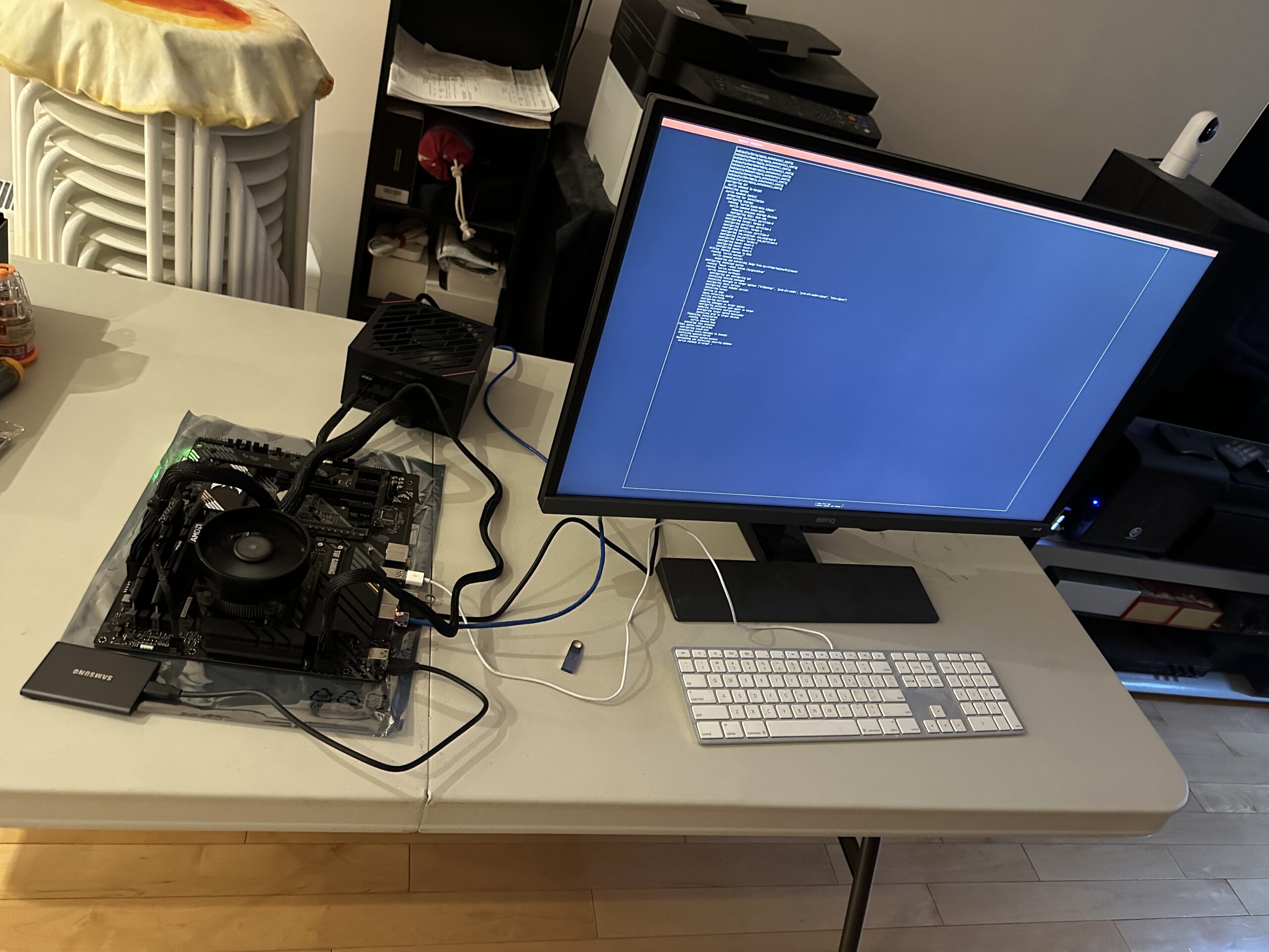
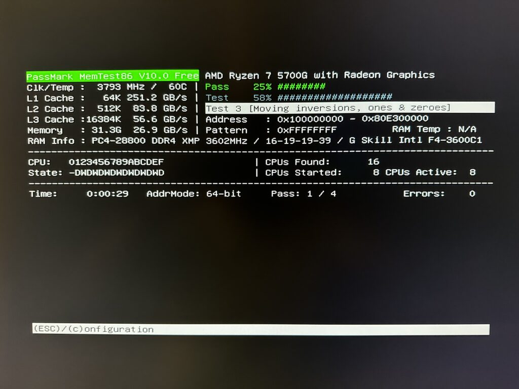
Test Setup
I quickly did a skeleton setup to make sure Ubuntu 22.04.01 Server Edition works with all hardware involved, especially the networking.
Memory Test
Once I know Ubuntu server is working good, I am now testing the server’s new 32GB DDR4 memory. This is running as I write this post and will let it run overnight.
The plan for tomorrow is to upgrade the current media server from Ubuntu 20.04.5 LTS to Ubuntu 22.04.1 LTS. Once this is done, I can then backup everything, and move the new hardware into the old casing and hope everything works.
This is going to be a fairly technical post on the topic of my Conext XWPro battery inverter configurations. I am writing this post primarily to document my experience and my current rationale, and for my future, forgetful self.
Previously I had my Grid Support SOC (State of Charge) and the Recharge SOC set to 40%. With these settings, the battery will be used (anytime during the day and night) until it discharged to 40%, which will initiate a charge cycle that will charge the battery back to 100%. Under normal circumstances, the battery will typically discharge during a very cloudy day, but mostly in the evenings and at night.
I had the above settings because I stupidly thought I should stay off the grid as much as possible. The intent is to try to charge the batteries in the evening during off peak hours, and not to use the grid at all during on peak hours. These settings certainly accomplish this, but at the expense of shortening battery life. Another big downside with this approach is that charging the battery through the Conext XWPro inverters only achieves around 83% efficiency. This observation is based on my real-time data observations from the actual inverters.
Yesterday I noticed that my batteries are reporting a State of Health (SOH) drop to 99% instead of 100%. This was a bit alarming given only 6 months of uses. I also realized from the Alectra invoices that Time of Use (ToU) is not a factor in Alectra’s billing calculations. All of this resulted in a shift in my thinking. We will now use the grid as our primary battery, and preserve our Lithium Ion as our backup batteries only. Time shifting of loads will no longer be my primary concern since it is no longer worth it with zero benefits.
To do this, I have set the Grid Support SOC to 90% and the Recharge SOC set to 85%. This way immediately after a charge cycle, the battery will be used a little bit to draw down from 100% to 90%. This has two benefits in my opinion. The first is to get some charge flow through the batteries, so it is not only sitting there. The second is that it leaves a 10% SOC gap. If we have a power failure during a sunny day, there is space for the excess solar production to go without tripping the solar inverters.
The 5% gap between Grid Support and Recharge is currently a guess. My thinking is that over time the charge on the Lithium batteries will leak and it will trigger a recharge cycle. Of course I did not want to set the Recharge the same as the Grid Support, because this will cause a constant recharge loop which defeats the purpose of preserving battery life. I do not know how long it will take to naturally draw down from 90% to 85%. This is why it is still a guess at this point. If there is no leakage, which is great news because it shows how good the batteries are, then I will have to trigger a recharge cycle at least once a month just to keep the charge flow within the battery’s chemistry.
For now I will live with the new settings and see how often the battery cycles. If it only cycles once every one or two months, then that is perfect. If it does not cycle through more than three months, then I may have to add the monthly charging cycle logic into my custom controller.
Our home Network Attached Storage (NAS) media server is going below 4 Terabytes of free space. The Seagate IronWolf 12TB hard drives were on sale with Amazon offering them below $300. I figure that I swap out two old 6TB drives with these new 12TB drives resulting in a net increase of a further 6TB of storage.
The last time this was done was around two years ago when I replaced 4TB and 6TB hard drives with 10TB hard drives.
So far the mdadm and LVM storage architecture has proven to be very flexible. I am able to mix drives of different sizes and able to grow our media storage volume over time.
Previously I had to make two swaps, each swap for each drive in the array. Effectively I am changing two 6TB drives for two 12TB drives because they are in a Raid 1 array. I cannot swap both at the same time, because I have to incrementally sync the data from the old drives to the new ones.
This has always been inconvenient because it means opening the physical server twice. However, this time I used my USB 3.0 HDD dock. I inserted one of two 12TB new drives into the dock, and then I temporarily created a three disks Raid 1 array. Once the sync is completed, which took 10+ hours, I remove one 6TB drive from the array configuration and I then physically replace both 6TB drives with both 12TB new drives in the server chassis, and place one old 6TB drive into the dock. The 6TB drive in the dock is the one that is still in the array configuration. I then add the second 12TB drive that is already in the server chassis to the three disk array. Once again, a sync is required to accommodate the second 12TB drive. This also took 10+ hours. Once the second sync is completed, I can finally remove the second 6TB drive in the dock from the array and have the array returned back to a two disk Raid 1 array.
The above description is probably quite confusing, but this technique allowed me to just have a single down time for the server instead of two when swapping hard drives in the server chassis.
There will be an additional downtime when I grow or resize the LVM volume and file system.
After this upgrade I should have the following Raid 1 (fully mirrored) arrays:
An array with 2 x 8TB
An array with 2 x 10TB
An array with 2 x 10TB
An array with 2 x 12TB
The above four arrays are combined into a logical volume using LVM that results in a total volume size of 40TB (fully mirrored) or a little over 36TiB of usable space (increasing from the old 31TiB).
We now have been running our net smart meter for more than a day now. I mentioned that we got our new net meter on this previous post.
Of course I am now curious how to read the meter so that I can decipher how much electricity we sent back to the grid. Here is a short video of what the meter is showing:
Meter Display Sequence
Initially the displayed information is quite cryptic, but looking at the meter’s label, I found this group of small prints.
These labels essentially tells us what is going on. The LED display cycles through 5 modes in total. The initial display is a segment test, which means all segments of the LED are displayed. This is a simple test to ensure that the LED display itself is functioning correctly. Next, it shows LST003, indicating that the next number it shows will be the amount of kWh of electricity that we ended up consuming or using. This is followed by LST004, another label indicating that the following number is the amount of kWh of electricity that is sent back to the grid.
Now with this new found knowledge, the above video shows that we used 13 kWh and exported 103 kWh since the meter was installed in the afternoon of May 4th.
In about 1.5 days, and bright sunny day yesterday, we generated and provided to our community electricity grid with a net of 90 kWh of energy.
Excerpt from the CBC article from Oct. 8th, 2021
There are 4 people in our house right now, and according to a recent CBC article our average carbon footprint is about 14.2 tonnes of CO2 per person. Doing a little more research, I found this white paper titled, “A Clearer View on Ontarios Emissions June 2019“. On page 8 of this paper, we see an annual average emissions factor (AEF) of 31 grams of CO2 per kWh. One tonne is 1,000,000 (a million) grams. This means to offset one individual, we need to offset 14,200,000 grams of CO2, and using the AEF this is equivalent to approximately 458,065 kWh!
To put this big number in perspective, I think our last month’s electricity bill only shows us using around 1,200 kWh of electricity.
It is clear that we will not be able to offset one of us, never mind all four of us by just using solar ourselves (at least not in Ontario). The idea of carbon neutrality is still a long ways off, and the above numbers show that we cannot do it alone. It will require every industry to do its part.
Update 2022-05-26 2:45pm: Took another reading outside. Used 313 kWh, Exported 1018 kWh, a net of 705 kWh. This with about 23 days of operation since May 04th.
Today is a good day. Alectra finally installed the net meter. From my previous post, I noted that without a net meter, any excess energy being sent back to the grid will be interpreted as usage. With the addition of the net meter, we can finally export our excess electricity from our solar panels without being charged for the generation. Instead, we can start earning and storing credits for the excess energy that we will supply to the grid.
Prior to the presence of the net meter, we gained plenty of experiences on going off grid. Effectively even on a cloudy day, we were able to generate enough energy for the house and charge our batteries to get us through the night. Below is a depiction of our energy utilization from Alectra.
Started to go off grid on April 23rd
The process of getting this net meter installed was not an easy feat! It took 22 days from the time of ESA inspection (April 12th) to Alectra installing the net meter. In summary, we played with the solar system to see what it can do for 11 days (April 12th to 22nd), while paying for the excess generation, and went off grid for the remaining 12 days (April 23rd to May 4th).
The small usages from the 23rd to the 30th that you see above were primarily charging our Toyota Prius Prime from the garage. That circuit is still grid tied and is independent of our Solar system. I cannot get an updated chart that contains data all the way up to today. Perhaps Alectra is doing something in the background in preparation for them to switch to net metering. In summary, we were pretty much off grid from April the 23rd to around 2pm today (May 4th). There was one exception, when we charged our backup batteries during off-peak hours from the grid on the evening of the 26th. We didn’t have to, but I was bit anxious with the battery at 50% whether it will last through the night and to the next evening, so this was more of an insurance. As we get more experience, we now have the confidence that even during cloudy / rainy days in the month of April, we should have no problem charging the batteries from solar that will last to the next night time operation.
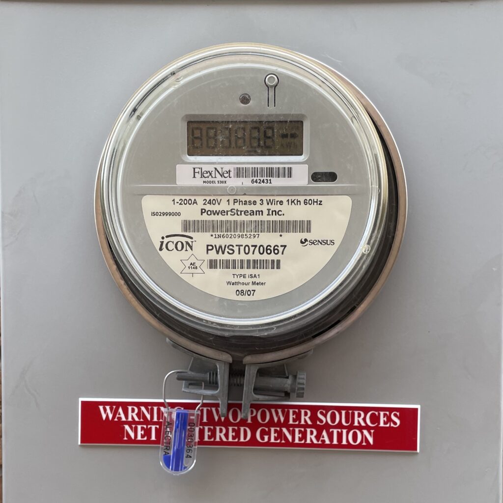
Our old unidirectional meter
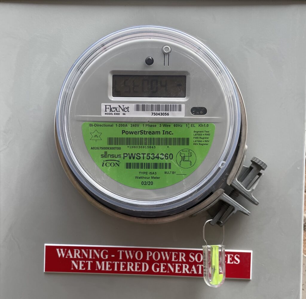
Our new bidirectional net meter
Once again, I have to thank New Dawn Energy Solutions for their correspondence and baby sitting the net meter installation process, as well as closing out the building permit from Richmond Hill. I am certain there was plenty of red tape that must be cut by them to get to where I am today, so kudos to them!
Today was also the day when we completed our second audit with Enertest. Once again Nick Crosby, A Certified Energy Advisor did a professional job. This audit is mandatory for the participation of the Canada Greener Homes Grant program.
If you are thinking of installing solar, New Dawn and Enertest are partners and experts in your endeavours.
In my previous post, all major installations were completed. Since that time, the ESA inspection was completed and we validated our batteries so that we have confidence that they will last for more than a day in the worst case scenario (no sun). However at the time of this writing, we are still waiting for Alectra Utilities to switch out our old meter to a new one that is net-meter capable. Until this meter replacement occurs, every watt-hour (Wh) of energy we produce and send back to the grid, Alectra will charge us for it as if we are using that energy instead of producing it. Here is a summary of the timeline from panel installation:
Solar panels installation completed on April 8th;
ESA Inspection on April 12th;
New LiFePO4 batteries installed on April 18th;
From April 18th onwards, we tested the system through a series of scenarios;
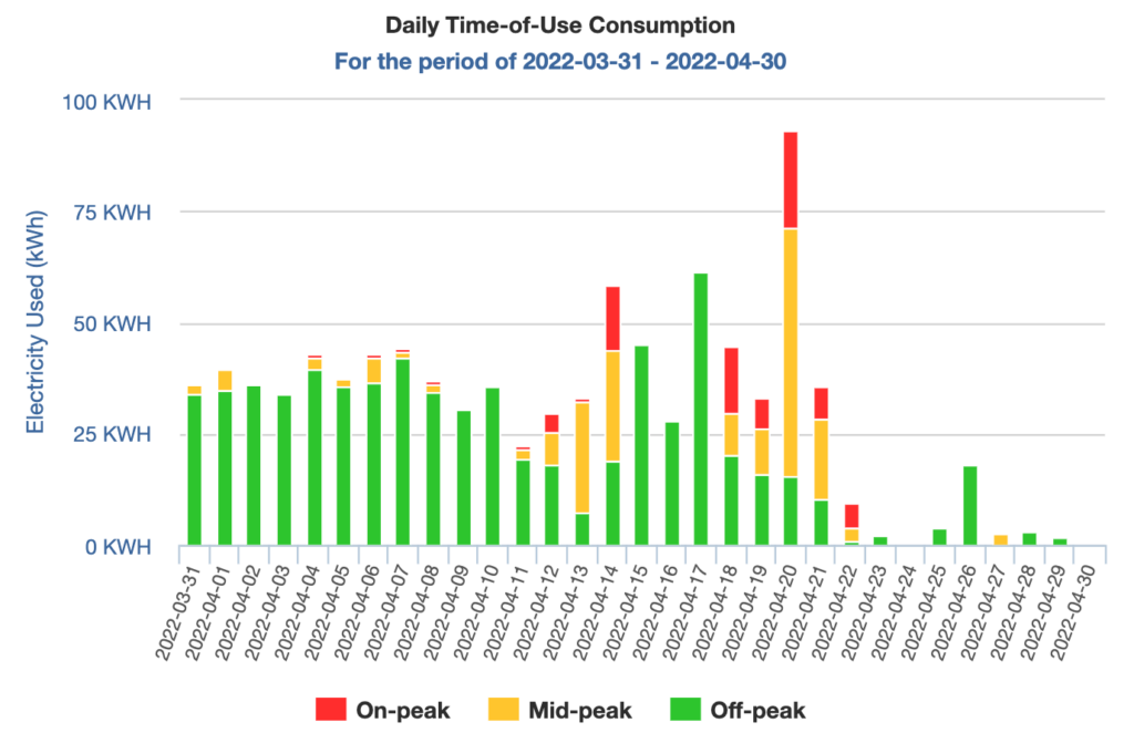
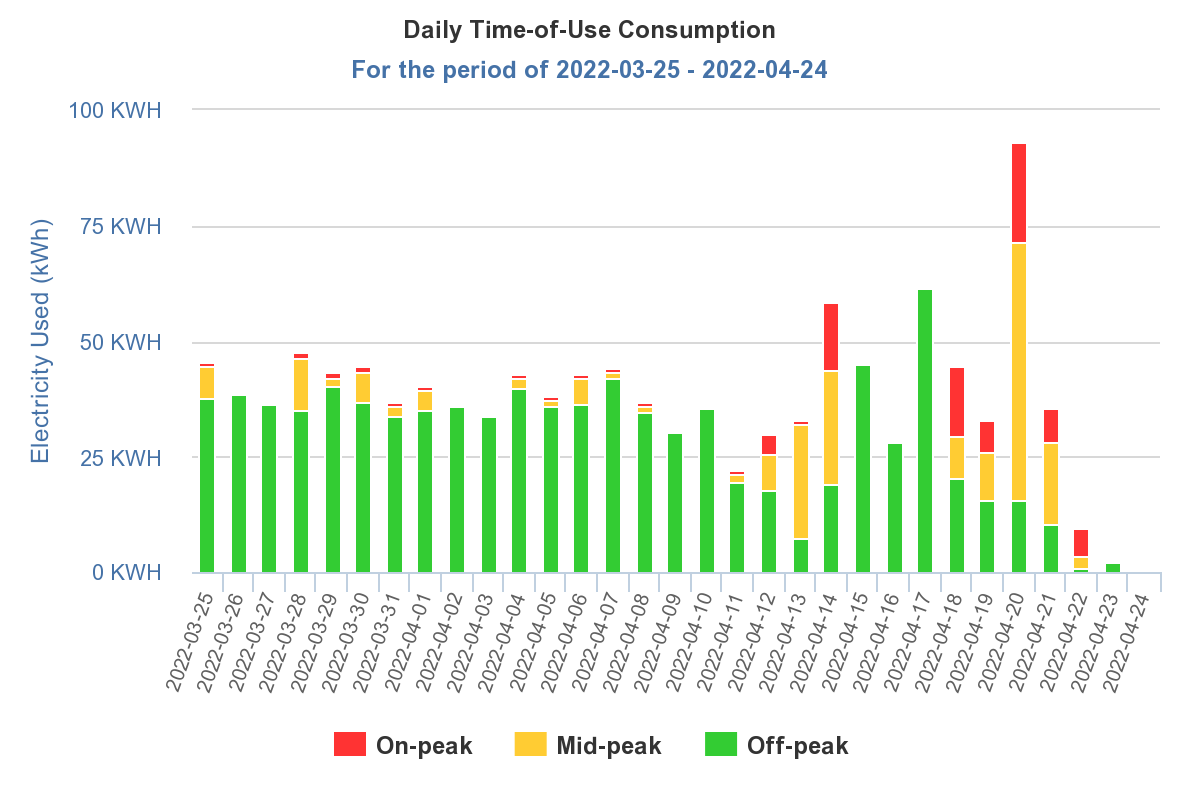
Our Utilization Chart from Alectra Utilities (click to enlarge)
So prior to the ESA inspection on April 12th, we continue our on-peak time shifting. You can see that there has been very little on-peak usage (red indicator) before April 12th. Once the ESA inspection is completed, we turned on our solar panels for the first time.
The erratic “usage” indicated in the above chart after April 12th, is a direct result of excess solar energy being exported back to the grid. Since our net meter has yet to be installed, Alectra sees it as usage, and unfortunately I will have to pay for that generation, very ironic if you ask me.
Nevertheless, we gathered much data in the last couple of weeks. We tested the system for both on grid and off grid operations. We tested with washer and dryer loads. Today on a bright sunny day, I even tried our air conditioner when we are off grid. The air conditioner started without any issues and worked with just solar energy, impressive. I will try again at night when we only use the batteries.
Let us take a look at our energy generation data that we collected so far. The information here is a surprise to us in a good way. The best way to show this is to provide the data for our best day performance to date.
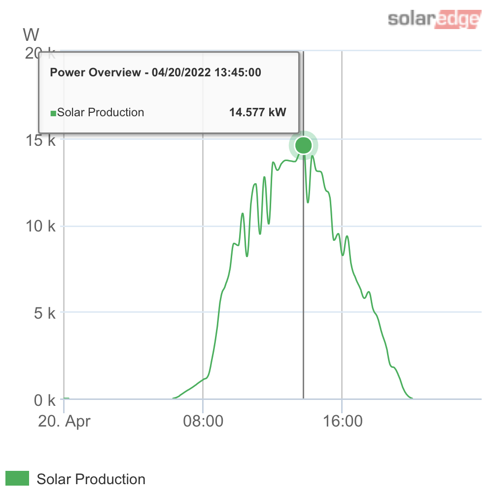
Our best performance day (April, 20th), 103.63 kWh generated
On April 20th we had a beautiful sunny day. We generated 103.63 kWh of electricity, since the house could not use it all, we fed most of it back to the grid. This is an excellent run and really show what the panels are capable of. For comparison, our average daily use is between 30 to 40 kWh. This means our solar generation ability on a sunny day can easily cover 2.5 to 3 days. For those Tesla drivers out there, we can generate enough power to fill your “tank”.
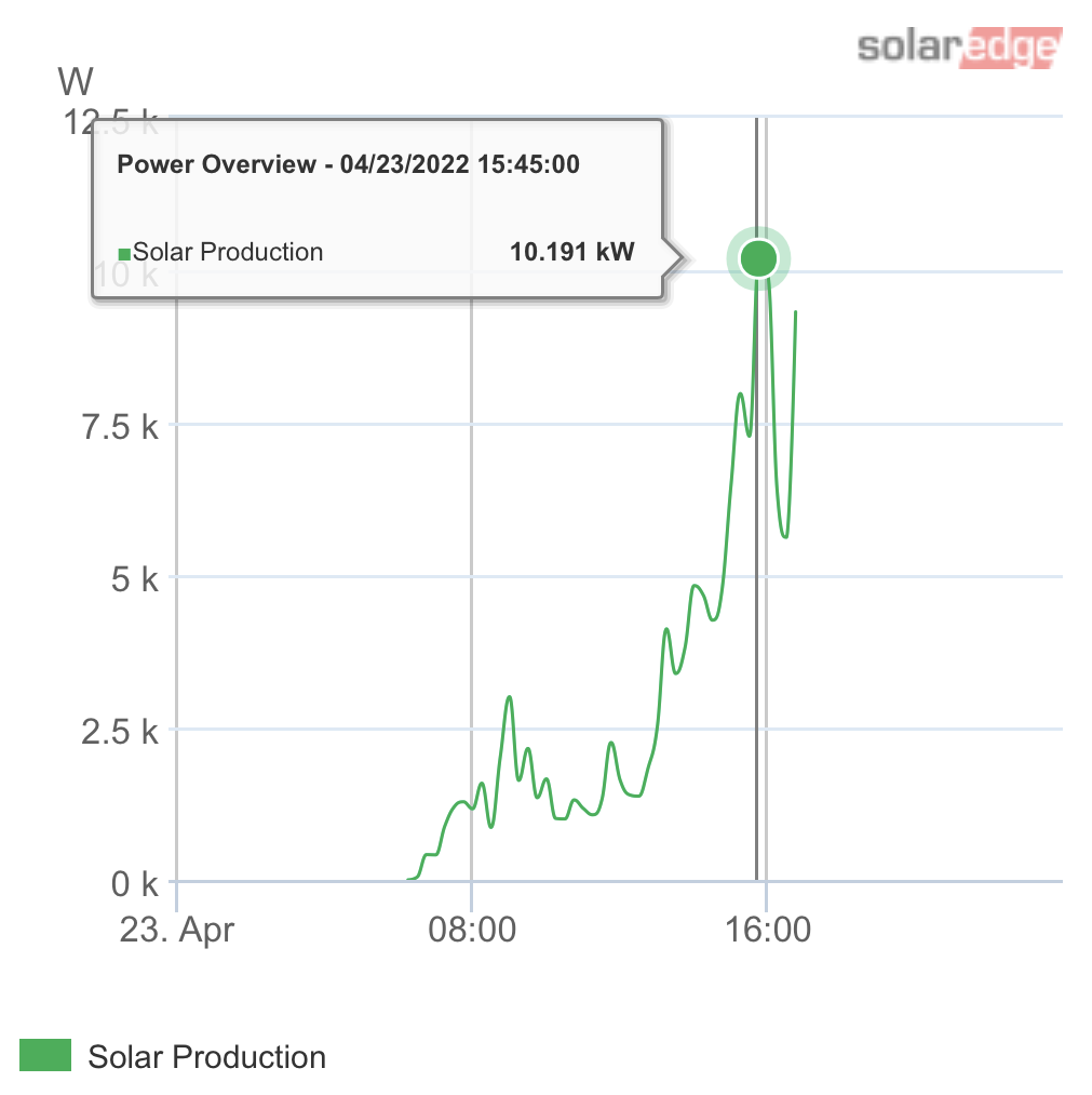
A rainy and cloudy morning and the sun came out at around 3pm. Total generation: 32.53 kWh (not whole day)
Yesterday was a rainy and cloudy morning, and the power generation on average kept up with house load usage. We woke up with the batteries at about 50% charged and the system managed to gain around 10% of battery charge at 3pm. After 3pm, the sun started to come out and the batteries charged rapidly. It easily reached 87% state of charge, and I had to shut the solar generation down at around 5pm, otherwise the energy would have no place to go, which leads to another major dilemma for off grid operation.
During on grid operation, the grid can regulate and absorb the excess energy generated by our solar panels. This is a huge convenience, which until we have the net meter, we really cannot take advantage of.
During off grid operation, we must use all the energy generated. Our supply must match demand and vice versa. This is where the batteries come in. They help to buffer or store the excess, and supplement any shortages. However, when the batteries are full and our usage cannot keep up with the generation, then the best option is to shutdown the solar, and shift our energy consumption to the batteries. Using the batteries will create more “empty” capacity, which we can later use to store more sun energy. I assumed, incorrectly, that this power regulation will be handled by the Schneider inverters. This is not the case, at least not fully. I am not going to go into details of Frequency Shift Power Control and other inverter deficiencies here, but suffice it to say that they are really not that smart. We will have to investigate on a more flexible power regulation mechanism for off grid operations in the future.
In the meantime, I have developed something myself that will monitor battery usage and solar power generation, so that I can determine when to turn on the solar and when to turn it off. Note that this is only for off grid operations. Once we have the net-meter, we can go back to on grid operations, and the convenience of the grid can act as the main regulator of power.
However, this is excellent experience as it teaches us some of the off grid challenges. There is no substitute for living through the experiences.
We hope the net-meter will arrive soon. Until then, we will challenge ourselves to see how many days we can stay off grid! You can already see our progress on the 23rd and the 24th of this month from the above Alectra utilization chart.