In a previous post, I described the hardware changes that I made to facilitate additional drive slots on my NAS Media Server.
We now need to migrate from an LVM system consisting of 40TB of redundant mirrored storage using mdadm to a ZFS system consisting of a single pool and a dataset. Below is a diagram depicting the logical layout of the old and the intended new system.
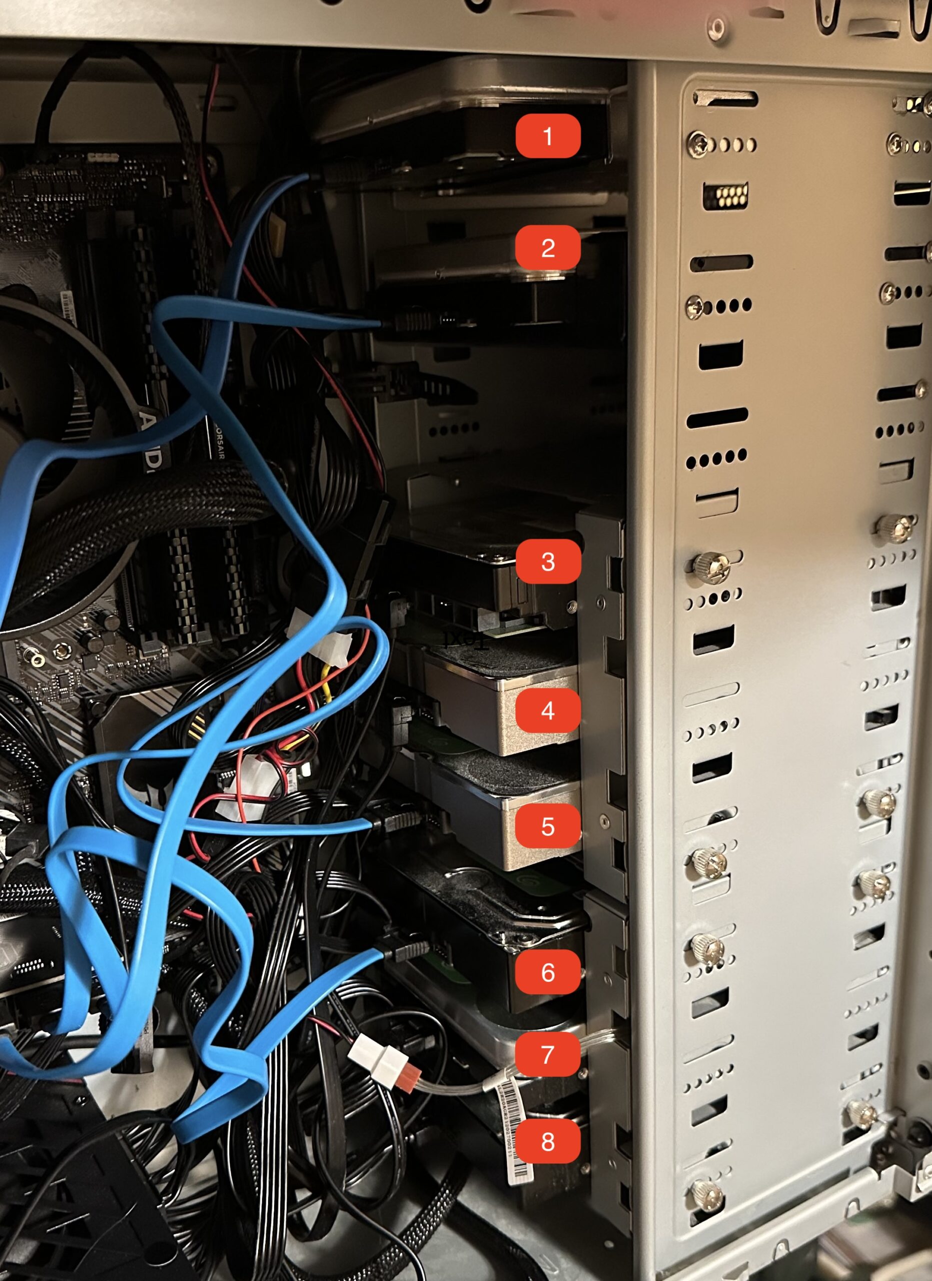
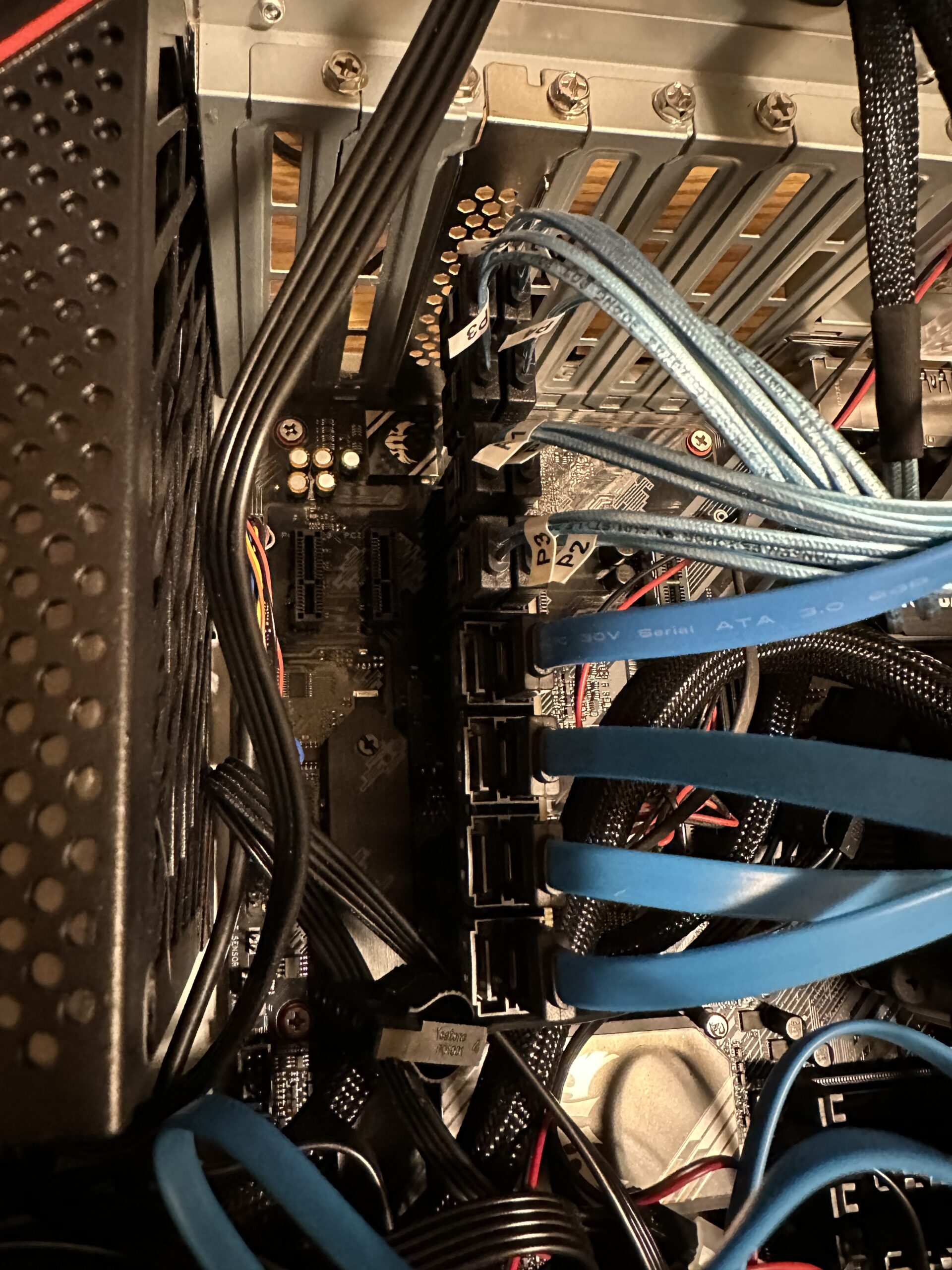
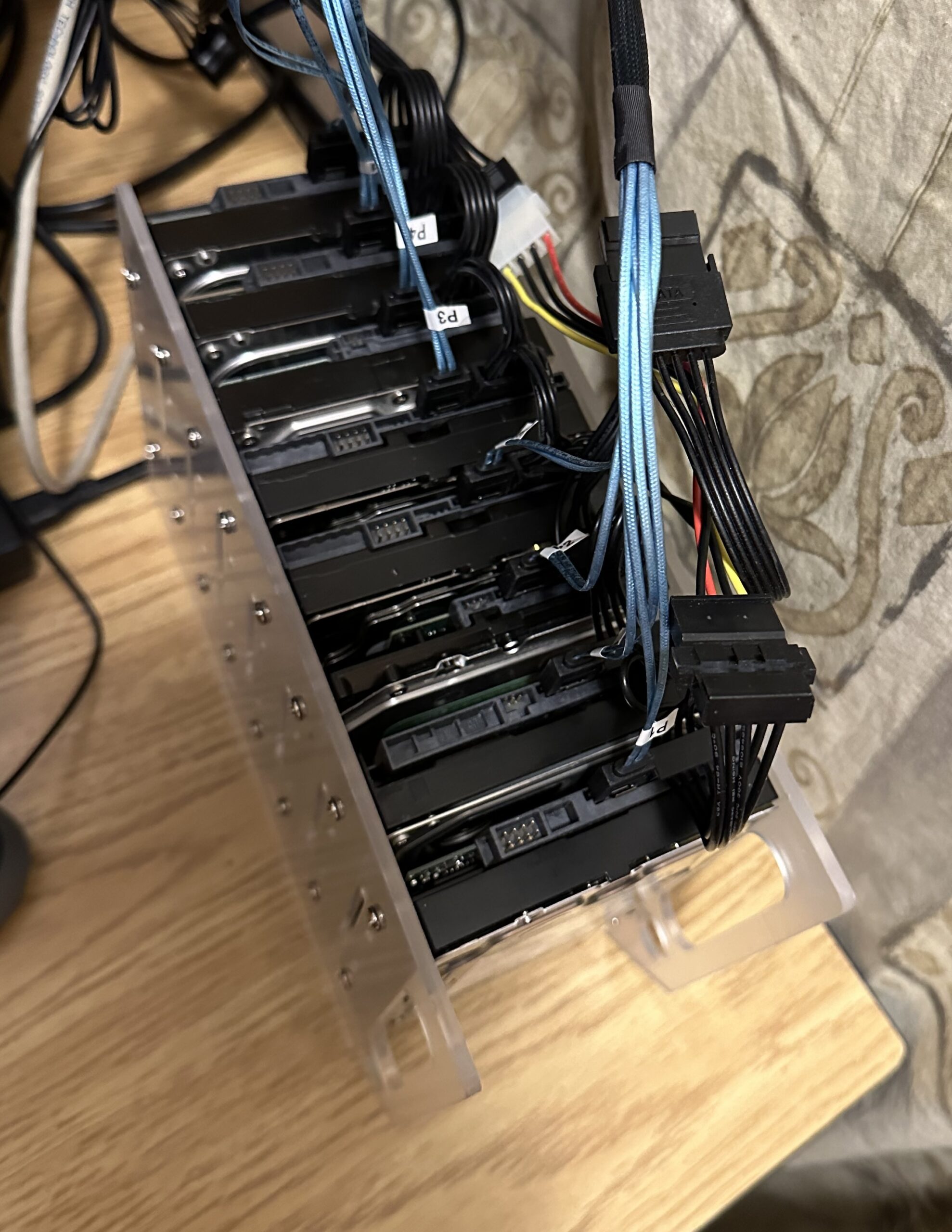
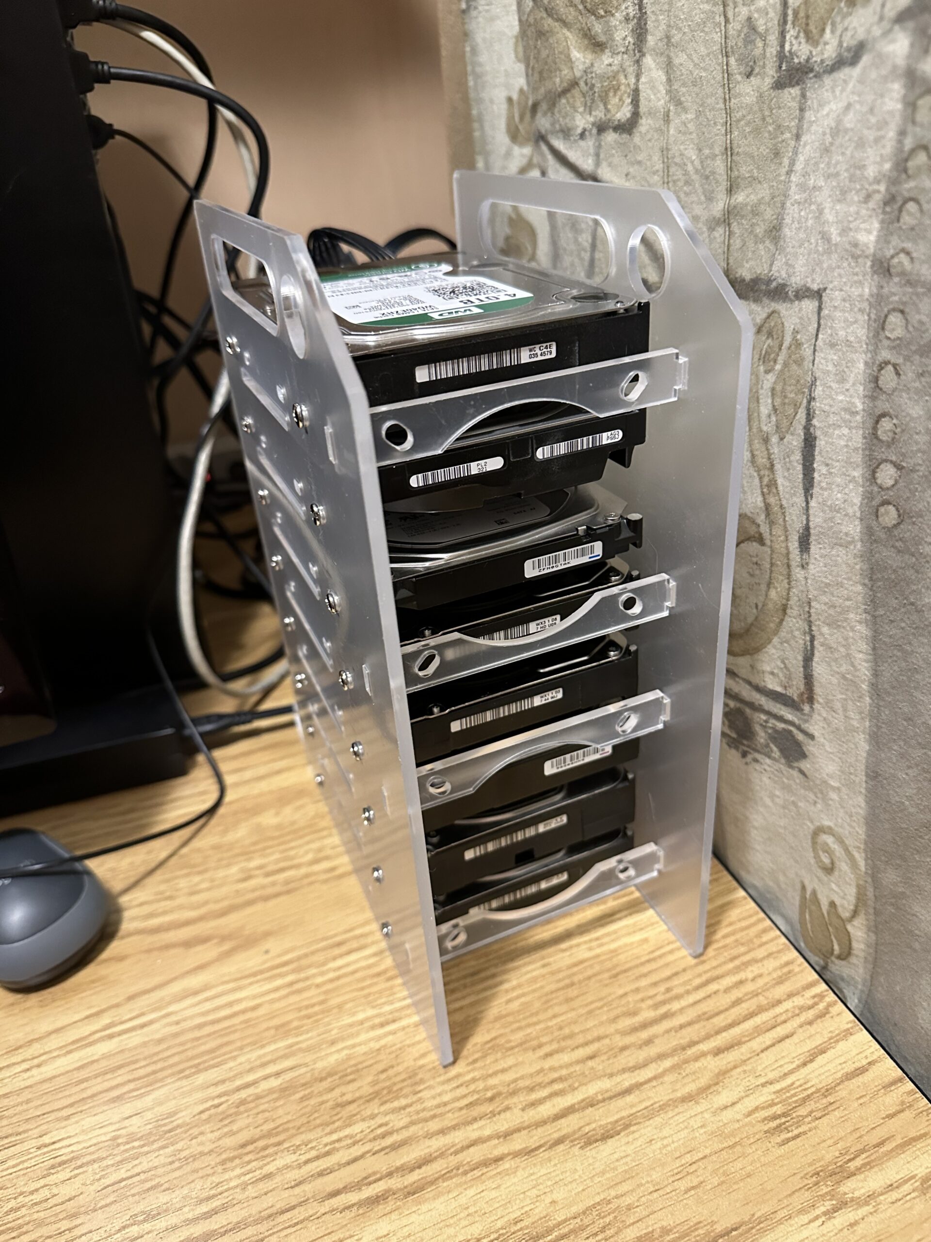
Before the migration, we must backup all the data from the LVM system. I cobbled together a collection of old hard drives and then proceeded to create another LVM volume as the temporary storage of the content. This temporary volume will not have any redundancy capability, so if any one of the old hard drives fails, then out goes all the content. The original LVM system is mounted on /mnt/airvideo and the temporary LVM volume is mounted on /mnt/av2.
I used the command below to proceed with the backup.
sudo rsync --delete -aAXv /mnt/airvideo /mnt/av2 > ~/nohup.avs.rsync.out 2>&1 &I can then monitor the progress of the backup with:
tail -f ~/nohup.avs.rsync.outThe backup took a little more than 7 days to copy around 32 TB of data from our NAS server. During this entire process, all of the NAS services continued to run, so that downtime was almost non-existent.
Once the backup is completed, I wanted to move all the services to the backup before I started to dismantle the old LVM volume. The following steps were done:
- Stop all services on other machines that were using the NAS;
- Stop all services on the NAS that were using the
/mnt/airvideoLVM volume;sudo systemctl stop apache2 smbd nmbd plexmediaserver
- Unmount the
/mnt/airvideovolume, and create a soft-link of the same name to the backup volume at/mnt/av2;sudo umount /mnt/airvideosudo ln -s /mnt/av2 /mnt/airvideo
- Restart all services on the NAS and the other machines;
sudo systemctl start apache2 smbd nmbd plexmediaserver
- Once again, the downtime here was minimal;
- Remove or comment out the entry in the
/etc/fstabfile that automatically mounts the old LVM volume on boot. This is no longer necessary because ZFS is remounted by default;
Now that the services are all up and running, we can then start destroying the old LVM volume (airvideovg2/airvideo) and volume group (airvideovg2). We can obtain a list of all the physical volumes that make up the volume group.
sudo pvdisplay -C --separator ' | ' -o pv_name,vg_name

  PV | VG
  /dev/md1 | airvideovg2
  /dev/md2 | airvideovg2
  /dev/md3 | airvideovg2
  /dev/md4 | airvideovg2
  /dev/nvme0n1p1 | airvideovg2
The /dev/mdX devices are the mdadm mirror devices, each consisting of a pair of hard drives.
sudo lvremove airvideovg2/airvideo
Do you really want to remove and DISCARD active logical volume airvideovg2/airvideo? [y/n]: y
  Flushing 0 blocks for cache airvideovg2/airvideo.
Do you really want to remove and DISCARD logical volume airvideovg2/lv_cache_cpool? [y/n]: y
  Logical volume "lv_cache_cpool" successfully removed
  Logical volume "airvideo" successfully removed

sudo vgremove airvideovg2
  Volume group "airvideovg2" successfully removed
At this point, both the logical volume and the volume group are removed. We say a little prayer to ensure nothing happens with our temporary volume (/mnt/av2), that is currently in operation.
We now have to disassociate the mdadm devices from LVM.
sudo pvremove /dev/md1
Labels on physical volume "/dev/md1" successfully wiped.
sudo pvremove /dev/md2
Labels on physical volume "/dev/md2" successfully wiped.
sudo pvremove /dev/md3
Labels on physical volume "/dev/md3" successfully wiped.
sudo pvremove /dev/md4
Labels on physical volume "/dev/md4" successfully wiped.
sudo pvremove /dev/nvme0n1p1
Labels on physical volume "/dev/nvme0n1p1" successfully wiped.
You can find the physical hard drives associated with each mdadm device using the following:
sudo mdadm --detail /dev/md1
#or
sudo cat /proc/mdstat
We then have to stop all the mdadm devices and zero their superblock so that we can reuse the hard drives to set up our ZFS pool.
sudo mdadm --stop /dev/md1
mdadm: stopped /dev/md1
sudo mdadm --stop /dev/md2
mdadm: stopped /dev/md2
sudo mdadm --stop /dev/md3
mdadm: stopped /dev/md3
sudo mdadm --stop /dev/md4
mdadm: stopped /dev/md4

# Normally you also need to do a --remove after the --stop,
# but it looks like the 6.5 kernel did the remove automatically.
#
# For all partitions used in the md device

for i in sdb1 sdc1 sdp1 sda1 sdo1 sdd1 sdg1 sdn1
do
	sudo mdadm --zero-superblock /dev/${i}
done
Now with all of the old hard drives freed up, we can repurpose them to create our ZFS pool. Instead of using the /dev/sdX reference of the physical device, it is recommended to use /dev/disk/by-id with the manufacturer’s model and serial number so that the ZFS pool can be moved to another machine in the future. We also used the -f switch to let ZFS know that it is okay to erase the existing content on those devices. The command to create the pool we named vault is this:
zpool create -f vault mirror /dev/disk/by-id/ata-ST10000VN0008-2JJ101_ZHZ1KMA0-part1 /dev/disk/by-id/ata-WDC_WD101EFAX-68LDBN0_VCG6VRWN-part1 mirror /dev/disk/by-id/ata-ST8000VN0022-2EL112_ZA1E8GW4-part1 /dev/disk/by-id/ata-ST8000VN0022-2EL112_ZA1E8S0V-part1 mirror /dev/disk/by-id/ata-ST10000VN0004-1ZD101_ZA2C69FN-part1 /dev/disk/by-id/ata-ST10000VN0004-1ZD101_ZA2964KD-part1 mirror /dev/disk/by-id/ata-ST12000VN0008-2YS101_ZRT008SC-part1 /dev/disk/by-id/ata-ST12000VN0008-2YS101_ZV701XQV-part1

# The above created the pool with the old drives from the old LVM volume group
# We then added 4 more drives, 2 x 6TB, and 2 x 4TB drives to the pool

# Adding another 6TB mirror:

sudo zpool add -f vault mirror /dev/disk/by-id/ata-WDC_WD60EFRX-68L0BN1_WD-WX31D87HDU09-part1 /dev/disk/by-id/ata-WDC_WD60EZRZ-00GZ5B1_WD-WX11D374490J-part1

# Adding another 4TB mirror:

sudo zpool add -f vault mirror /dev/disk/by-id/ata-ST4000DM004-2CV104_ZFN0GTAK-part1 /dev/disk/by-id/ata-WDC_WD40EZRX-00SPEB0_WD-WCC4E0354579-part1
We also want to add the old NVMe as ZFS L2ARC cache.
ls -lh /dev/disk/by-id/nvme-Samsung_SSD_970_EVO_Plus_500GB_S4P2NF0M419555D

lrwxrwxrwx 1 root root 13 Mar  2 16:02 /dev/disk/by-id/nvme-Samsung_SSD_970_EVO_Plus_500GB_S4P2NF0M419555D -> ../../nvme0n1

sudo zpool add vault cache /dev/disk/by-id/nvme-Samsung_SSD_970_EVO_Plus_500GB_S4P2NF0M419555D
We can see the pool using this command:
sudo zpool list -v vault

NAME                                                    SIZE  ALLOC   FREE  CKPOINT  EXPANDSZ   FRAG    CAP  DEDUP    HEALTH  ALTROOT
vault                                                  45.4T  31.0T  14.4T        -         -     0%    68%  1.00x    ONLINE  -
  mirror-0                                             9.09T  8.05T  1.04T        -         -     0%  88.5%      -    ONLINE
    ata-ST10000VN0008-2JJ101_ZHZ1KMA0-part1                -      -      -        -         -      -      -      -    ONLINE
    ata-WDC_WD101EFAX-68LDBN0_VCG6VRWN-part1               -      -      -        -         -      -      -      -    ONLINE
  mirror-1                                             7.27T  6.49T   796G        -         -     0%  89.3%      -    ONLINE
    ata-ST8000VN0022-2EL112_ZA1E8GW4-part1                 -      -      -        -         -      -      -      -    ONLINE
    ata-ST8000VN0022-2EL112_ZA1E8S0V-part1                 -      -      -        -         -      -      -      -    ONLINE
  mirror-2                                             9.09T  7.54T  1.55T        -         -     0%  82.9%      -    ONLINE
    ata-ST10000VN0004-1ZD101_ZA2C69FN-part1                -      -      -        -         -      -      -      -    ONLINE
    ata-ST10000VN0004-1ZD101_ZA2964KD-part1                -      -      -        -         -      -      -      -    ONLINE
  mirror-3                                             10.9T  8.91T  2.00T        -         -     0%  81.7%      -    ONLINE
    ata-ST12000VN0008-2YS101_ZRT008SC-part1                -      -      -        -         -      -      -      -    ONLINE
    ata-ST12000VN0008-2YS101_ZV701XQV-part1                -      -      -        -         -      -      -      -    ONLINE
  mirror-4                                             5.45T  23.5G  5.43T        -         -     0%  0.42%      -    ONLINE
    ata-WDC_WD60EFRX-68L0BN1_WD-WX31D87HDU09-part1         -      -      -        -         -      -      -      -    ONLINE
    ata-WDC_WD60EZRZ-00GZ5B1_WD-WX11D374490J-part1         -      -      -        -         -      -      -      -    ONLINE
  mirror-5                                             3.62T  17.2G  3.61T        -         -     0%  0.46%      -    ONLINE
    ata-ST4000DM004-2CV104_ZFN0GTAK-part1                  -      -      -        -         -      -      -      -    ONLINE
    ata-WDC_WD40EZRX-00SPEB0_WD-WCC4E0354579-part1         -      -      -        -         -      -      -      -    ONLINE
cache                                                      -      -      -        -         -      -      -      -  -
  nvme-Samsung_SSD_970_EVO_Plus_500GB_S4P2NF0M419555D   466G  3.58G   462G        -         -     0%  0.76%      -    ONLINE
Once the pool is created, we wanted to set some pool properties so that in the future when we replace these drives with bigger drives, the pool will automatically expand.
zpool set autoexpand=on vaultWith the pool created, we can then create our dataset or filesystem and its associated mount point. We also want to ensure that the filesystem also supports posixacl.
zfs create vault/airvideo
zfs set mountpoint=/mnt/av vault/airvideo
zfs set acltype=posixacl vault
zfs set acltype=posixacl vault/airvideo
We mount the new ZFS filesystem on /mnt/av because the /mnt/airvideo is soft-linked to the temporary /mnt/av2 volume that is still in operation. We first have to re-copy all our content from the temporary volume to the new ZFS filesystem.
sudo rsync --delete -aAXv /mnt/av2/ /mnt/av > ~/nohup.avs.rsync.out 2>&1 &This took around 4 days to complete. We can all breathe easy again because all the data now have redundancy again! We can now bring the new ZFS filesystem live.
sudo systemctl stop apache2.service smbd nmbd plexmediaserver.service
sudo rm /mnt/airvideo
sudo zfs set mountpoint=/mnt/airvideo vault/airvideo
sudo systemctl start apache2.service smbd nmbd plexmediaserver.service

zfs list

NAME             USED  AVAIL     REFER  MOUNTPOINT
vault           31.0T  14.2T       96K  /vault
vault/airvideo  31.0T  14.2T     31.0T  /mnt/airvideo
The above did not take long and the migration is completed!
df -h /mnt/airvideo

Filesystem      Size  Used Avail Use% Mounted on
vault/airvideo   46T   32T   15T  69% /mnt/airvideo
Getting the capacity of our new ZFS filesystem shows that we now have 46TB to work with! This should last for at least a couple of years I hope.
I also did a quick reboot of the system to ensure it can come back up with the ZFS filesystem in tack and without issues. It has now been running for 2 days. I have not collected any performance statistics, but the services all feel faster.