
We have a cat named Darci. During the summer time she likes to take strolls through our backyard, checking out other frequent visitors like rabbits, chipmunks, squirrels, birds, and the like. She does this on an extended leash so to avoid her chasing these visitors and get lost into the wild. If you are curious, then visit her on Instagram.
We of course turn on the air conditioner on most days of the summer, so when Darci wants to come back into the house, she sits by the backyard sliding door and await one of us to open the door for her. If we are busy, she waits patiently for quite some time. My wife came up with the door bell idea. Instead of scratching the glass pane of the sliding door, which is mostly silent, we will train her to hit a door bell, which will alert us to let her in.
This is how I was assigned the Darci Door Bell project. This is another excellent opportunity to create a gadget. My first thought is to create a Raspberry Pi with a camera that uses an AI image classifier on the backend. I thought this would be a good opportunity to get my feet wet in AI. However, when dealing with a camera, and a Raspberry Pi, we are now talking about power and the need to be “plugged in”. We wanted a gadget that is wireless and battery operated. A battery based solution will severely restrict the power budget, so back to a WiFi based remote door bell idea.
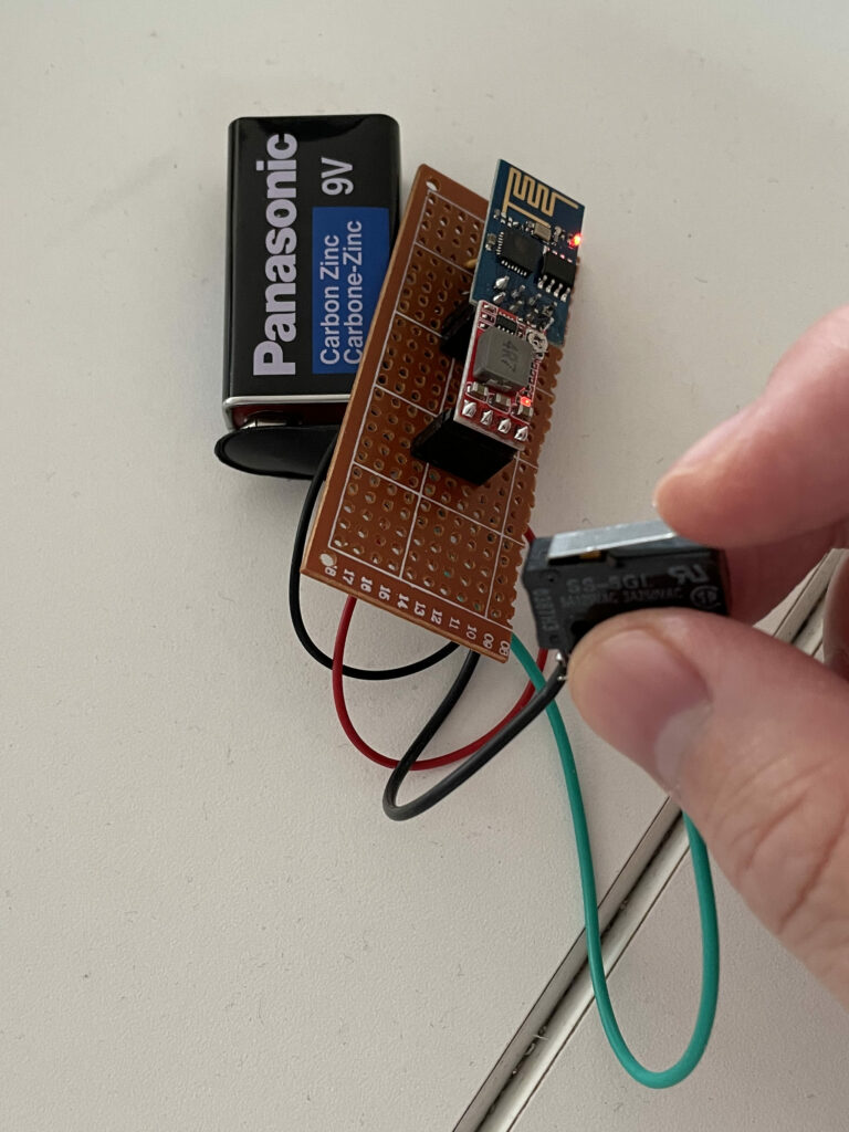
After more research, I decided to use an ESP8266 MCU with WiFi and a simple step-down buck converter to convert 9V to 3.3V. I had worked with the ESP8266 before when I was attempting to use it to create my garage door opener. That was over six years ago. ESP8266 just came out and has yet to be integrated into the Arduino platform. Today, it is now much easier to work with the ESP8266. Using the Arduino IDE, one can simply program the ESP8266 natively as an MCU without even requiring an Arduino board.
From a previous project, I built a small circuit using an USB FTDI interface that will accept the ESP8266 ESP-01 board. This way I can plug the ESP8266 using USB to my computer and program it with the Arduino IDE. I wrote the following sketch, and programmed the ESP8266 ESP-01 board.
 #include <ESP8266WiFi.h>
 #include <ESP8266HTTPClient.h>

 #define SERVER_IP "192.168.1.111"

 #ifndef STASSID
 #define STASSID "myssid"
 #define STAPSK  "adsjfkdajfioeujfngjhf"
 #endif

 void setup() {

   WiFi.begin(STASSID, STAPSK);

   while (WiFi.status() != WL_CONNECTED) {
     delay(250);
   }

   WiFiClient client;
   HTTPClient http;

   // configure traged server and url
   http.begin(client, "http://" SERVER_IP "/IOTHandler.php"); //HTTP
   http.addHeader("Content-Type", "application/x-www-form-urlencoded");

   // start connection and send HTTP header and body
   http.POST("id=darciButton");

   http.end();

   ESP.deepSleep(0);
 }

 void loop() {
   ESP.deepSleep(0);
 }
The above program is pretty simple. When the board wakes up, it connects to my WiFi and then send an HTTP-POST request to my server that will handle the request based on the id, which in this case, it will be darciButton. As soon as the request is sent, the MCU will go into a deep sleep.
This way, the door bell will be a physical button that is hooked to the RST pin of the ESP8266 causing the ESP8266 to boot and send this POST request and immediately goes to sleep. The deep sleep is important, because while the device is in this deep sleep mode, the current draw from the 9V battery is negligible (<< 1mA). The only time the battery is used is when the button is pressed and released, and the ESP8266 is sending out the POST request. Using this power conservation approach, it is my hope that the 9V battery will last for the entire year of operation.
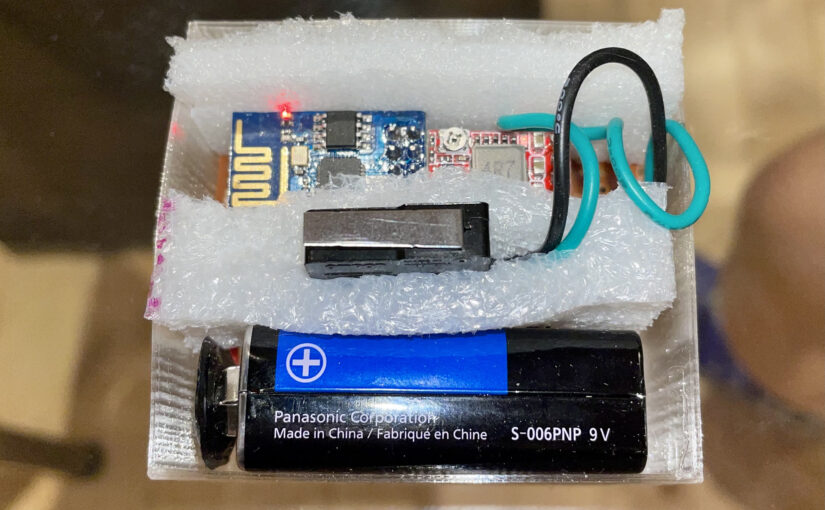
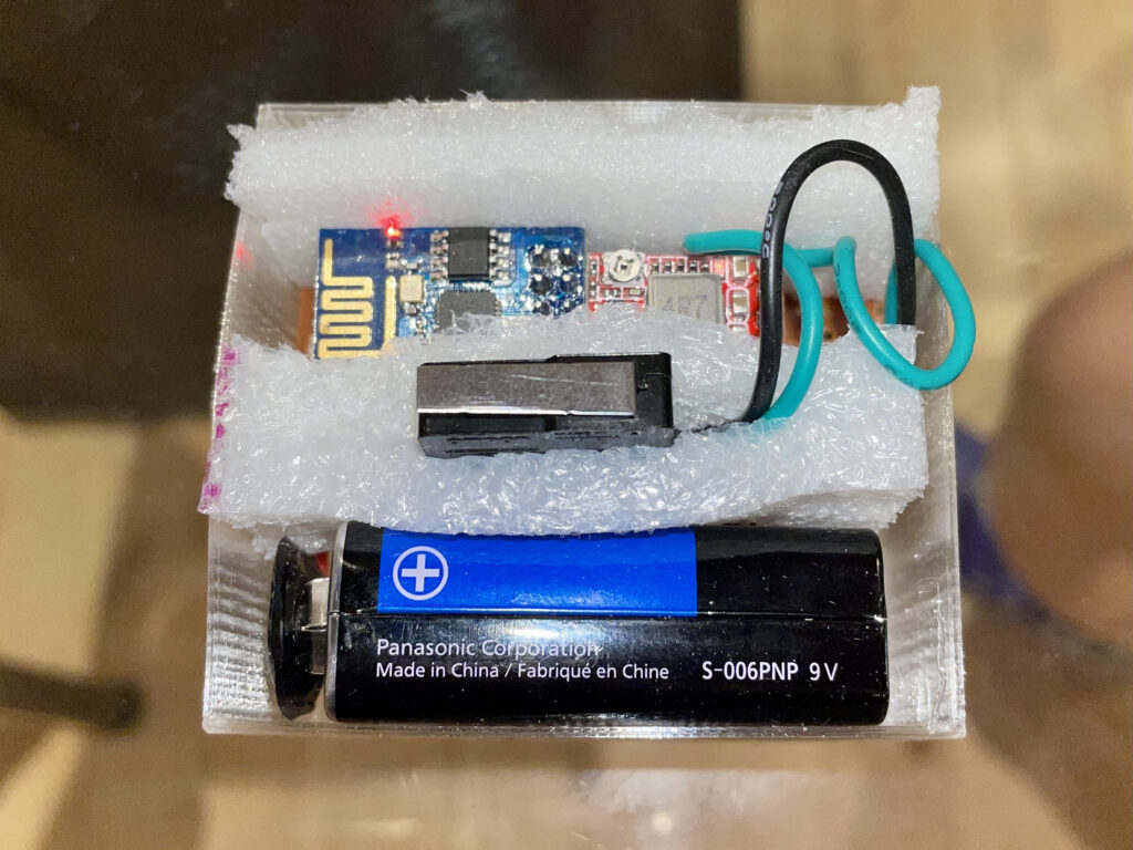
I used my 3D printer to print a little box for the whole thing and gave it some packaging padding, making sure the switch is on the top and properly supported. The final result looks something like this.
We then created a cardboard top cover that snugly fit the box, so that the top cover can freely move up and down the containing, plastic box. The switch itself has a little spring to it that allows the top cover to return back to its original position after being pressed. The finished product looks like this:

The top cover has a nickel on there so that Darci has a good target to train on.
Remember the server receiving the POST request? Well, I did some simple php programming on the server so that once the POST is received, I send out another HTTP request. This time to the Homebridge server with the homebridge-button-platform plugin installed. Homebridge is something that I already have and use to connect all non-compliant HomeKit accessories so that I can use those accessories via Siri. With this new plugin, I can connect this custom WiFi button to the HomeKit ecosystem within the house.
In effect, whenever this button is pressed, my HomeKit service will register an accessory button being pressed, and I can program a HomeKit scene that gets executed. I programmed a scene to play an audio file on all of my HomePods in the house. The audio file plays an audible door bell twice which I previously added to my Music library.
The final reward as shown by Darci herself. Watch the video below:
Of course with the button hooked up to HomeKit, we can now use this wireless button to do whatever HomeKit can do, unlock doors, turn lights on or off, etc. We will explore those possibilities in the future.