This is going to be a fairly technical post on the topic of my Conext XWPro battery inverter configurations. I am writing this post primarily to document my experience and my current rationale, and for my future, forgetful self.
Previously I had my Grid Support SOC (State of Charge) and the Recharge SOC set to 40%. With these settings, the battery will be used (anytime during the day and night) until it discharged to 40%, which will initiate a charge cycle that will charge the battery back to 100%. Under normal circumstances, the battery will typically discharge during a very cloudy day, but mostly in the evenings and at night.
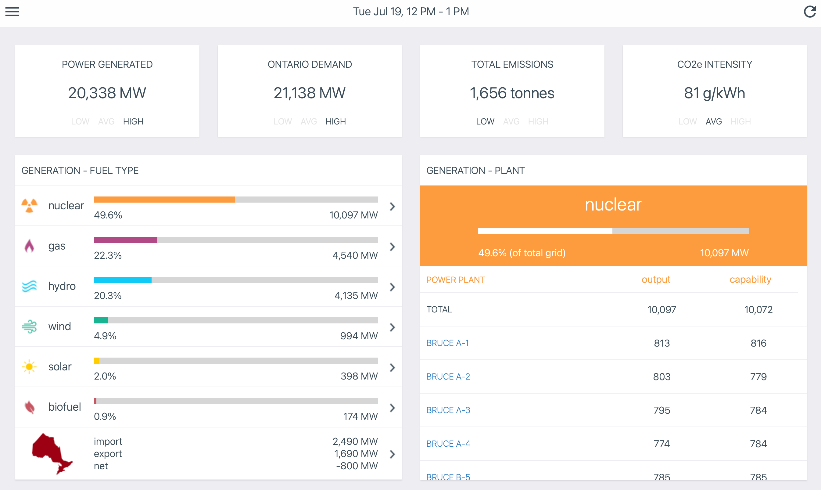
I had the above settings because I stupidly thought I should stay off the grid as much as possible. The intent is to try to charge the batteries in the evening during off peak hours, and not to use the grid at all during on peak hours. These settings certainly accomplish this, but at the expense of shortening battery life. Another big downside with this approach is that charging the battery through the Conext XWPro inverters only achieves around 83% efficiency. This observation is based on my real-time data observations from the actual inverters.
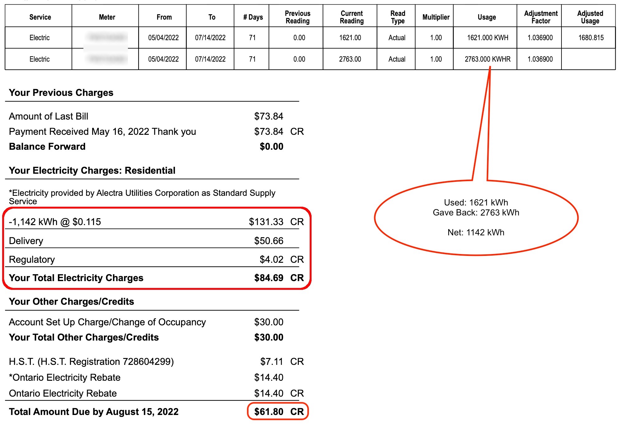
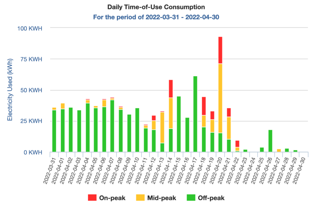
Yesterday I noticed that my batteries are reporting a State of Health (SOH) drop to 99% instead of 100%. This was a bit alarming given only 6 months of uses. I also realized from the Alectra invoices that Time of Use (ToU) is not a factor in Alectra’s billing calculations. All of this resulted in a shift in my thinking. We will now use the grid as our primary battery, and preserve our Lithium Ion as our backup batteries only. Time shifting of loads will no longer be my primary concern since it is no longer worth it with zero benefits.
To do this, I have set the Grid Support SOC to 90% and the Recharge SOC set to 85%. This way immediately after a charge cycle, the battery will be used a little bit to draw down from 100% to 90%. This has two benefits in my opinion. The first is to get some charge flow through the batteries, so it is not only sitting there. The second is that it leaves a 10% SOC gap. If we have a power failure during a sunny day, there is space for the excess solar production to go without tripping the solar inverters.
The 5% gap between Grid Support and Recharge is currently a guess. My thinking is that over time the charge on the Lithium batteries will leak and it will trigger a recharge cycle. Of course I did not want to set the Recharge the same as the Grid Support, because this will cause a constant recharge loop which defeats the purpose of preserving battery life. I do not know how long it will take to naturally draw down from 90% to 85%. This is why it is still a guess at this point. If there is no leakage, which is great news because it shows how good the batteries are, then I will have to trigger a recharge cycle at least once a month just to keep the charge flow within the battery’s chemistry.
For now I will live with the new settings and see how often the battery cycles. If it only cycles once every one or two months, then that is perfect. If it does not cycle through more than three months, then I may have to add the monthly charging cycle logic into my custom controller.